After the weather zapped the output transistor (a BS150 FET) of my Ultimate3S beacon from QRP-Labs yet again, I was forced to replace the device, again. It is not a difficult job at all, just a little chore. This time I decided to make it easier on myself. Instead of replacing the transistor by soldering it in, I decided to use a plug-in base so that I can just whip it out and plug in a new one.
The bad guy
The offending object is shown clearly out of focus, just to gain some perspective. I always solder mine in with at least 5mm long legs sticking out above the PC Board to allow for fitting a heat sink.
Decapitated
Decapitate the weakling in one go! Don’t waste time, just stick in the cutter and cut out the weakling, but do it as far away from the PCB as possible, leaving the stumps for later removal. I placed a small piece of paper behind the legs to make it easier to see in the picture.
Now you can just heat the legs one-by-one and tap the board so the legs will drop out. Easy.
IC Sockets
Next, consult your trusty junk box or buy some of these IC sockets. They can be any number of pins from 8 to 28, it doesn’t matter. I just happened to have 8-pin variants in stock. Avoid the cheap ones with the single flat blades that pushes to one side of the IC only.
Cylindrical pins
This is what you want. These cylindrical (or tubular) legs will make good contact with the FET’s legs and they are tapered and coated so your connection is guaranteed to be solid.
Three Pins
Solder three pillars into the three required holes. I managed to keep the front two pillars together and the back pillar is separate due to space constraints. You might even put a drop of glue to hold everything together, but that isn’t necessary and I didn’t do it.
In Place
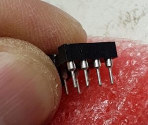
Cut the FET legs a little bit shorter, but not too short, and plug it into the sockets. Make sure it goes down all the way and is oriented correctly.
You can see a close-up view of FET in position at the start of this article.
Completed
Admire your work upside-down and from the side, making sure everything fits correctly.
Put back your heat sink, close the covers and away you go!
While WSPR’ing across multiple bands (“band hopping”) has been done before, I thought it might be interesting to do five different modes on the same band. It was easier done than said! Argo SlowHell callsign
I was sitting with a customer’s QRP-Labs Ultimate3S beacon on my bench, all built up and ready to test. It was a single band version with the LPF for 40m installed. Nicely constructed and in perfect working order.
After sweeping the filter and adjusting the LCD brightness and setting the output bias (all of 5 minutes – these are very easy beacons to build) I wondered what I could do as a “torture test” because WSPR’ing on 40 meters is so … common?
It occurred to me that if I can’t jump to five or six different bands, why don’t I jump to five different modes?
And that, as they say, is how the fight started.
Setting your Frames
Before using the Ultimate3S beacon, you have to enter your callsign and a few other basic details. The little Ultimate3S beacon has two pushbuttons on the front with which you can set and select your choices, by running through a menu system. I see it as two separate tasks (I’ll explain below) and a little bit of preparation will help you along nicely.
The first decision you should make is how often you want to repeat your message(s). There is an informal arrangement to repeat a WSPR message not more frequently than 10 minutes, with 20 minutes probably a better choice.
To start with, let us hypothetically hop to 5 bands:
Each WSPR frame takes about two minutes and must start exactly on an even minute boundary. I have arbitrarily decided to start on top of the hour at 00:00:00, and each consecutive transmission will start on the next two-minute boundary e.g.
00:00:00 First transmission frame – 40m WSPR
00:02:00 Next transmission frame – 30m WSPR
00:04:00 Next transmission frame – 20m WSPR
00:06:00 Next transmission frame – 15m WSPR
00:08:00 Next transmission frame – 10m WSPR
00:10:00 Beacon calibrates after each transmission cycle
This is how we used to do it for “WSPR-2” but it is very important to note that each mode has its own peculiarities and for example JT9/JT65 may use 1 minute frames and WSPR-15 uses 15 minute frames. I’m using WSPR-2 to make things simpler.
Task One: Choose your Cycle
In the above example you will notice that the last transmission starts exactly on the eighth minute and lasts for almost two minutes. There is barely 5 seconds left before the tenth minute begins. This is a BIG problem because the beacon needs time to calibrate the synthesizer, an activity which can take 30 seconds or 60 seconds or whatever you have chosen in your setup. Clearly, if the beacon starts exactly on the tenth minute, it will still be busy with calibration when the wake-up horn blows for the next cycle. Bad news!
Thus, in the above example I could choose a 12-minute cycle, which is fine (six cycles per hour), but it might just be better to give it a small break and start your next cycle on 20 minutes into the hour, leaving a few minutes for breathing space.
On the other hand, nothing prevents you from running a hard 24 x 7 x 365 schedule with no breaks. It is not a technical issue, it is just good manners to leave a break.
Task Two: Choose the contents of your Frames
Now that we have an idea of how long we want to make our cycle, we can decide the payloads for each frame. As I said before, if we want to only do WSPR we would end up with five frames like we did in Figure 1.
However, if we only have one band with only one LPF (Low Pass Filter) fitted, we can choose to hop between modes. The little Ultimate3S can do 18 modes standard out of the box, and some of those modes even have sub-modes.
A simple choice would be to target the more popular modes that are easily spotted. Let us put WSPR in the first frame, followed by a QRSS frame, then some SlowHell which is a gorgeous mode, then a CW-ID because it might be good manners and finally a JT65B because I have never heard what it sounds like.
Here is a concept:
Starting on the top of the hour again:
00:00:00 First transmission frame – 40m WSPR
00:??:00 Next transmission frame – 40m QRSS
00:??:00 Next transmission frame – 40m SlowHell
00:??:00 Next transmission frame – 40m CWID
00:??:00 Next transmission frame – 40m JT65B
00:??:00 Beacon calibrates after each transmission cycle
Notice I didn’t put times for the frames, because I have no idea how long each mode takes. I could sit down with a sharp pencil and a calculator and attempt to work it out, but hey it is just so much easier to actually program the above sequence and measure how long each one takes, and this is what I found.
First, QRSS:
Putting this all together I assembled the following cycle with a duration of less than 20 minutes:
Start Duration Frame / Mode
00:00:00 2 min First transmission frame – 40m WSPR
00:02:00 6 min Next transmission frame – 40m QRSS
00:07:00 8 min Next transmission frame – 40m SlowHell
00:16:00 secs Next transmission frame – 40m CWID
00:17:00 1 min Next transmission frame – 40m JT65B
00:18:00 1 min Beacon calibrates after each transmission cycle
18 minutes cycle time (more or less)
To cut a long story short, if I set my cycle time to 20 minutes I should be able to get through all five frames and have a small safety margin. This is what I finally programmed (with approximate times):
Figure 4: Mode-Hopping with Frequencies
Conclusion
This was a very interesting exercise and it worked out so well. I’m still changing some of the frequencies (e.g. SlowHell) to find locations that are easier to spot, but that is simply fine-tuning to the already working concept.
Should you be interested in obtaining my “Cheat-Sheet” for the above setup, please do not hesitate to contact me and I’ll email you a copy.
73s de ZR6LU Leon Uys from Johannesburg 0825735580
PSDRAnd in other news, I’m trying to play with this cute little SDR receiver (the cuteness which I am sharing with you in another post), but I’m having mega problems.
Don’t get me wrong: The issue is not SDR or this cute little Rx. I own and operate a Flex-1500 which has quietly become my almost all-time favourite desktop radio. Software Defined Radios are just awesome. I can install Virtual Audio Cables and serial port replicators and connectors in all the configurations I’m using. I have also played extensively with other variations of hardware kits over time and I would like to think that I’m not an expert but that I can make successful contacts with a SDR.
Thus, when I needed to squeeze an experimental (not top-of-the-line) and not very good (yet) but definitely tiny (as in physically small) receiver into my Ultimate 3S beacon from Hans Summers over at QRP-Labs, I bought a PSDR module from my friend Anton Janovsky over at Giga. Measuring a fractional 30mm x 40mm the size was exactly right, and it requires a 12v input which I already feed to the Ultimate 3S so that wasn’t going to be a problem. The receiver itself wasn’t going to win any awards for noise or quality, the circuit is a simple Johnson counter with 7474 circuit group and Tayloe detector circuits – more info over at Pandatron. No filters or pre-selection or anything, but good enough for a proof of concept prototype. I might even use the pre-existing LPF filters with a bit of cutting and soldering to the boards.
The really exciting thing is that in the latest Ultimate 3S from QRP-Labs with the Si5351A synthesizer, it is a piece of cake to tap another output from the frequency generator and use that as the LO (Local Oscillator) input to the PSDR module. A very elegant solution emerges! Forge ahead and spend the money!
To cut a long story short the issue is that the modern laptops don’t have stereo (yes, two channel) inputs. Google it and sift through the millions of hits. The best summary I found was at temporaryland dated 2008 over at his website of rm42 called “Consumer alert – Sound-Mix intentionally crippled laptops” in which he explains that for reasons that makes no sense, modern laptops can only record in MONO from their built-in sound cards. And in the case of Lenovo, maybe they are scared of the DRM police, but they made it a HARDWARE limitation.
This is important to me, as the PSDR gives out I/Q signals similar to just about any other experimental SDR kit, it needs TWO signals to the processor. Ultimately (pun intended) in the Ultimate 3S I was going to consider using the Analogue inputs’ A/D converter to pick up the sounds for me although I’m not there yet in the design.
But to hit the wall so early with such a silly limitation is simply stupid. There is a work-around – buy an external USB sound card like the STLab M330 (only 16 bits). But that is an unnecessary expense and extra wires to plug in and extra things that can go wrong. Needless to say, I’m no longer a Lenovo fan.
So the point of this message is: For the moment, if you want to play with I/Q signals from a SDR receiver, make sure you have a stereo line input. From there, SDRSharp will make your life easy. But without the underlying hardware you are screwed.
I let the U3s run last night with the first LPF relay board installed (6 bands only) and hopping in sequence from 80m to 10m just to see what can happen. I’m still learning the device, she is not a trivial little kit! I added a CW ID as the last transmission.
Anyways to my surprise two major discoveries: The single output transistor is not overheating – thats gotta be good. And then some spotters uploaded my callsign! This is amazing because the bands were a little bad. To see my signal going as far as 8000km on only 200mW (I didn’t actually measure the 200mW, I’m just assuming) is a great accomplishment.
The little worry is that it appears to drift a little on 10m, only 3 Hz or so, but still … I wanted to put up a 2m beacon sometime and the drift is not good. Mind you, I haven’t done anything to stop it, there are some hint’s on Hans Summers’ blog site.
Meanwhile, maybe it is time to build the OCXO (Oven Controlled Crystal Oscillator) and see if that brings an improvement.
Ultimate 3 S
My latest baby! I will write the full story in a few installments, from the back to the front so to speak, in other words I’ll show you the final result first before going back and showing pictures of the construction and so on.
Of course I’m talking about my Hans Summers Ultimate 3S beacon transmitter.
She came to me via the UK, where Ken Murdoch put it into his luggage and transported it to me in the far south over the December 2015 holiday period. Thus we avoided any issues with the South African Post Office who is notorious for “losing” packages.
After some construction time, not a lot I might add, she lit up her lights and started WSPR-ing sweet tones to the world. ZS6USA was the first to respond.
It is possibly the best kit I’ve ever built and the sweetest performer I can remember.
The last thing I did last night was to make peace between my laptop, my Flex-1500 SDR, and the various VAC and VSP drivers and whatever else was struggling to co-exist in the apparently too small memory of my Windows 7 computer.
So can you imagine the delightful surprise I got this morning: I switched everything on and went to make coffee and shower. A little bit later I went to check on my WSPR installation, and this is what I saw on the log:
I’m very pleased, because my antenna is not really made for 80m (it’s actually a 40m travelling wave Broadgun) and I wasn’t expecting any spots yet. But there it is, and more than once. Nice spot!
This is what makes this hobby so great, these little achievements.
QRSS on ArduinoQRSS is not something I knew anything about, until I stumbled across a useful use for my Arduino: A small daughter board (called a shield) with a few components to turn it into a QRSS transmitter.
I admit I am lazy and morse code is way out of my reach – know the joke? did it once and didn’t like it? Similarly I had never heard a QRSS signal until I built and tested my module. But once it was up and running I started to become a little more interested in trying to decipher the morse code. And once that got going, I couldn’t help but try to listen out for other QRSS callsigns.
There is a lot of information on QRSS on the internet, so I will only comment on my own experiences. Firstly, the kit was easy to build.
X1M Digimaster ComboInterfacing a Xiegu X1M 5 watt QRP HF transceiver to a G4ZLP Digimaster Pro3 to go digital and portable on the HF bands, by Leon Uys ZR6LU.
I recently obtained a Xiego X1M HF radio from OM Rory in Port Elizabeth. Nice package and works SSB out of the box. I took it with me to Parys on a weekend (it was small enough to sneak it into my baggage without the XYL noticing) and working off a 12v/7Ah gelcel battery I managed a few contacts by stringing a piece of wire into a nearby tree. Signal reports were around 57, not surprising as it only puts out 5 watts. Reception was ok but I was slightly bothered by the background noise especially on 40m and I had no way to filter it out or reduce it (see more later).
Remember I was calling QRP or Portable, as I was deliberately working off-grid. I wanted to be able to pack my stuff into a small backpack and carry it with me – not quite RaDAR, yet, but certainly testing the limits of what can be achieved in a light weight package. Thus, getting a 57 report was actually a compliment to me.
To put things in perspective, the X1M is more-or-less a competitor to the Yaesu FT-817. I should say less, because it is a lot cheaper but it also lacks a lot of very nice, often essential features. Like DSP audio filtering. More about that later. But overall you get what you pay for and I am satisfied that it works as advertised.
So my next challenge was to get on the air with digital. My ultimate goal is to work PSK31 off a small 12v battery to some exotic island! I have no idea if that is even achievable but I’m certainly going to test the waters!
Working digital is not strange to me, as I have a permanent station set up at my home QTH. I have two home-built modems that give excellent results, and my Yaesu FT-840 is permanently connected to a Broadgun Travelling Wave antenna (multi-band) about 10 meters above ground. Pushing about 50 watts before the ALC kicks in, I have worked most continents and I’m chasing a DXCC since September 2013. I use my other radio, a Yaesu FT-857 with a 400 watt linear when needed, more for voice but it is also occasionally roped in for PSK use. My logging is done with Ham Radio Deluxe and DM870. Easy and comfortable.
So question 1: Which interface? Scouring the internet I see the Tigertronics SignaLink gets the thumbs-up from many people. Importing into South Africa is technically easy but very expensive in local currency. More so because the Post Office service is non-existent and we have to use couriers which can easily double the actual dollar cost of an interface. But hey, if it is good enough for other hams, it is good enough for me, right?
Wrong! The SignaLink was a big disappointment. Oh, it is an excellent sound card interface, and I have kept mine after playing with it. It works. But it doesn’t have a CAT or any form of computer interface! Sadly it is only a sound card interface with no capability to interface to a serial or USB-serial port. And, guess what, if you run HRD with DM870 it is almost essential that you have that capability. Now I could have added yet another converter box to my collection of cables and boxes. I’m already unpacking several transformers and cables and goodies every time I set up station and one more would not be an issue.
G3ZLP Digimaster Pro3But why struggle with fixing things, trying to make them work, when there is an excellent ready-made off-the-shelf solution? Enter the Digimaster ProThree from G4ZLP Electronics: The most awesome (and may I add easiest to set up) interface money can buy today.
Just for the record, my Digimaster Pro3 arrived in-country at Customs within 48 hours after placing my order. It was working in my shack within hours after delivery. And the support was even faster. It is an excellent device.
So now we have the pieces of the puzzle on the table – a 5 watt HF radio, a sound card, a serial port (for easy logging) and lots of enthusiasm, but nothing actually connects together! Since there is no real instruction manual for tying together this odd collection of stuff, my approach was to test each component individually before attempting to create fireworks.
X1M RS232The first test was to add a USB-to-Serial converter between my laptop and the radio. I used a spare Arduino board from my junkbox as a RS-232 to 5v converter (“Xbee USB adapter” link below) and simply wired up the 3 wires with jumpers: Ground, Rx data and Tx data. Set up HRD as an ICOM 718 and wow! Everything works, I can read or change frequencies and bands and it is really exciting.
Next I needed to see if the audio quality from the earphone was usable. This was very quick and easy, I simply used a 3.5mm headphone patch cable to go from the “Headphone” socket on the rear of the X1M radio to the “Microphone” socket on the laptop. Running HRD / DM870 I could see some signals on the waterfall display. Audio should be sufficient.
MFJ-561 CW PaddleNow a short diversion to use my MFJ-561 miniature travel iambic CW paddle to see if the radio can click into CW mode and if a kind of PTT arrangement would be possible. Success again, the X1M works nice on CW. Most of the “Plug-and-Pray” experiments are now done. I think we have a possible winner.
But I want to use a single black box (pun not intended) for interfacing, and so out comes the Users Guide for the G4ZLP Digimaster Pro3. Actually, just the pin connections on page 4 for the 6-pin mini-DIN connector. A quick e-mail to Noel (I told you the support is awesome) to confirm that the CAT interface is already at 5 volt, and the soldering of the two interface cables commence.
This next two steps involve pulling out the soldering iron. Step 1: Make a serial cable.
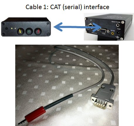
X1M CAT cableA full schematic with pictures is provided in the appendix, but essentially a 3-wire cable is soldered up that links the 3.5mm CAT interface on the Digimaster Pro3 to the 9-pin Serial connector on the back of the X1M transceiver: Ground, Rx data, TX data. I kept my wire short to reduce the possibility of RF interference.
Step 2: Make a sound and PTT cable.
This time around it is a two-header cable: From the 6-pin mini-DIN connector make a short audio cable for the speaker connector on the back of the radio (two wires), and then make a second cable to the front mic connector on the X1M. I am taking the wires through a ferrite bead scavenged from an old Sony camera cable to reduce possible interference.
Fire up the works and you should be ready to go! I found that the volume controls on the Digimaster Pro3 are quite sensitive, and you should follow the general instructions on the G4ZLP site carefully. My PTT is the virtual COM-port and the transmit audio is set for 0dB gain in HRD. I am including screen shots for reference.
I have one concern that I must mention so far: The little X1M radio does not have AGC or DSP, so the audio quality is very noisy from all the pops and crackles and adjacent signals cause interference. Maybe in a follow-up project we can try to do something about that.
Happy PSK’ing! See you on the QRP bands soon.
73s
de Leon Uys ZR6LU
________
References:
1. Xiego X1m Radio http://www.eham.net/reviews/detail/11065
2. Tigertronics SignaLink http://www.tigertronics.com/
3. Digimater Pro3 by G4ZLP Electronics http://www.g4zlp.co.uk/unified/DigiMaster_ProThree.htm
4. Rory ZS2BL SA Ham Shack http://www.commco.co.za/sarl.htm
5. Yahoo! Groups X1M Tranceiver http://groups.yahoo.com/neo/groups/X1M_QRP-Transceiver/conversations/messages
6. RS232-to-USB Serial 5v Adapter http://www.dfrobot.com/index.php?route=product/product&product_id=72#.UsCCo_uupCq
7. MFJ Enterprises, CW Travel Paddle http://www.mfjenterprises.com/Product.php?productid=MFJ-561
DigiMaster Pro3The next critical piece in my quest to become completely QRP-Portable arrived on Friday afternoon. No sooner did I arrive home than I ripped open the box, ignored the instructions, and promptly proceeded to connect and use my new sound card and CAT interface – a DigiMaster Pro3 from G4ZLP. Happiness knows no boundaries!
Now to tell the story truthfully I will have to go back in time a little: In fact about 4 months ago on 1st July 2013 I made my first PSK31 contact with a home-built interface (CAT and Sound). Since then I managed to capture about 100 contacts in 30 countries with that interface and radio: A Yaesu FT-840 running 30-50 watts into a Broadgun Travelling Wave wire antenna not more than 10 meters above ground. A major motivator was Noel Hammand ZR6DX who explained the inner workings of HRD at the West Rand Club (www.zr6wr.co.za) and which brought me up to speed in no time. Remember that it was winter by us and the conditions were very poor, so eking out even a modest signal from the ether was tough.
Nevertheless, I built a second interface (different schematic) for my second (mostly voice) radio, a Yaesu FT-857D (CAT and sound). It also worked well and I probably made one or two contacts with it. I also purchased a USB-CAT cable for the FT-857D so that I could independently check my construction or test some configurations. I was having major fun! I even worked a local ZS-land PSK competition and learned a lot about logging and QSL’s and stuff.
And then the trouble started. Sigh. I became convinced that the reason I wasn’t building a country list faster, was because either my home-built interface or my laptop was NOT GOOD ENOUGH … you know the story?
Step one: Replace the sound card. I purchased a small USB Sound Card dongle from the local computer shop. While it worked and I made a contact or two, nobody told me my signal was any better than before. I was very disappointed but of course I convinced myself that it was a cheap chinese product.
So the next step was to thrust my hand deep into my pocket and but a brand new SignaLink. I plugged it in and except for a small misunderstanding about functionality (the SignaLink is only a sound card, not a combined CAT interface) it worked well. But I was disappointed yet again – nobody gave me a better than before signal report. AFter spending all that money I can emphatically say the expensive brand-name interfaces perform no better than a proper home-built interface. The SignaLink is a nice device though, and the volume control knobs are cute to twist while fiddling.
But the job wasn’t done yet: I needed to be completely portable, and that implied QRP. Radio, and laptop. All battery operated. I already own the laptop – a very nice Lenovo X1 Carbon UltraBook. This is one of those Brand-New Super-Thin Ultra-Light laptops that runs for 8 hours on a recharge and weighs next-to-nothing. And I own a reasonable rig – the Yaesu FT-857D is not very light but can go down to 5 watt. I only needed an interface that uses ONE USB CABLE. I started to realise that my nice laptop had one shortcoming: It only has two USB ports. One is used by the mouse, and the second one MUST drive the sound card as well as the CAT interface. Since the SignaLink is sound only, I continue my quest.
Two devices jump out from the crowd: The DigiMaster Pro3 from G4ZLP (UK) and the RigBlaster Advantage from West Mountain Radio (USA). Both are very capable devices, both get good reports, and both are overseas (read=EXPENSIVE SHIPPING). Eventually I contacted both suppliers and to be honest I made the decision on price: Shipping from the USA was just a litte more expensive. I sent my credit card details to G4ZLP Electronics and lo and behold a few days later my shiny new apparatus arrived in the mail. It took me minutes to rip it out of the box, throw away the instructions, and start using it. I added 7 new countries in one evening before even looking at the instructions.
The DigiMaster Pro3 deserves a review on its own and I will do that in a follow-up post. However, I can say without a shadow of doubt that the sound quality (and thus the signal quality) is pretty much the same as any USB sound card. The real benefit for me, and the reason I love the DigiMaster, is that I can now use one USB port on my laptop to drive the radio’s CAT interface plus the Sound Card. It does that very well.
And yes, it is awesome to twiddle the sound knobs.