I managed to get my hands on a few of the latest (2020) QCX Plus kits from QRP-Labs and as usual I had no difficulty finding homes for the extra kits, obviously keeping one for myself to build in the wee hours of the morning when it is quieter.
It was – as always – an easy build and I finished in maybe 3.5 hours. The documentation is good and the components even better.
I love building kits and maybe if I am lucky I will win the competition over at The SWLing Post for a MFJ-8100K shortwave receiver kit. That would be an awesome complementary radio!
After the weather zapped the output transistor (a BS150 FET) of my Ultimate3S beacon from QRP-Labs yet again, I was forced to replace the device, again. It is not a difficult job at all, just a little chore. This time I decided to make it easier on myself. Instead of replacing the transistor by soldering it in, I decided to use a plug-in base so that I can just whip it out and plug in a new one.
The bad guy
The offending object is shown clearly out of focus, just to gain some perspective. I always solder mine in with at least 5mm long legs sticking out above the PC Board to allow for fitting a heat sink.
Decapitated
Decapitate the weakling in one go! Don’t waste time, just stick in the cutter and cut out the weakling, but do it as far away from the PCB as possible, leaving the stumps for later removal. I placed a small piece of paper behind the legs to make it easier to see in the picture.
Now you can just heat the legs one-by-one and tap the board so the legs will drop out. Easy.
IC Sockets
Next, consult your trusty junk box or buy some of these IC sockets. They can be any number of pins from 8 to 28, it doesn’t matter. I just happened to have 8-pin variants in stock. Avoid the cheap ones with the single flat blades that pushes to one side of the IC only.
Cylindrical pins
This is what you want. These cylindrical (or tubular) legs will make good contact with the FET’s legs and they are tapered and coated so your connection is guaranteed to be solid.
Three Pins
Solder three pillars into the three required holes. I managed to keep the front two pillars together and the back pillar is separate due to space constraints. You might even put a drop of glue to hold everything together, but that isn’t necessary and I didn’t do it.
In Place
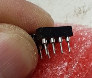
Cut the FET legs a little bit shorter, but not too short, and plug it into the sockets. Make sure it goes down all the way and is oriented correctly.
You can see a close-up view of FET in position at the start of this article.
Completed
Admire your work upside-down and from the side, making sure everything fits correctly.
Put back your heat sink, close the covers and away you go!
QCXSo yesterday (it was a Sunday) I had a lot to do, but nothing more important than to cut open the wrappings of the 20m QCX kit that I purchased from QRP-Labs a few months ago. Yes, it was still lying in its protective wrappings after all this time. Work is seriously interfering with my hobbies.
At first when I shook out all the packets with all the little parts into a tray (standard practise), it was a little intimidating. It wasn’t just a small Ultimate3S kit which I can build with my eyes closed in less than an hour. Instead of taking shortcuts (which the documentation warns against) I decided to follow the manual. That in itself was the best advice ever – the 138 page manual is clear and laid out in logical order.
I did take a few shortcuts, purely because I have one of those cute assembly rigs where you can insert the components, hold then in place with a foam block, then flip it over to solder all the leads at once. I did all the caps in the first round, and all the resistors second round. I have a habit of checking each solder joint when I snip the wire and in this case the unit worked first time.
The slowest part of the construction was the toroids. Not because it is difficult, but because my eyes are not so good any more and I have to work under the magnifying light which restricts movement a little. Each one of the 8 wires must be inserted in the correct hole with a tweezer or small longnose.
My PCB is a version 1 so I did the two recommended modifications.
All-in-all a very viable kit and very enjoyable to build and use. I particularly liked the idea of the little microswitch “hand-pump” which gave me no end of giggles.
While WSPR’ing across multiple bands (“band hopping”) has been done before, I thought it might be interesting to do five different modes on the same band. It was easier done than said! Argo SlowHell callsign
I was sitting with a customer’s QRP-Labs Ultimate3S beacon on my bench, all built up and ready to test. It was a single band version with the LPF for 40m installed. Nicely constructed and in perfect working order.
After sweeping the filter and adjusting the LCD brightness and setting the output bias (all of 5 minutes – these are very easy beacons to build) I wondered what I could do as a “torture test” because WSPR’ing on 40 meters is so … common?
It occurred to me that if I can’t jump to five or six different bands, why don’t I jump to five different modes?
And that, as they say, is how the fight started.
Setting your Frames
Before using the Ultimate3S beacon, you have to enter your callsign and a few other basic details. The little Ultimate3S beacon has two pushbuttons on the front with which you can set and select your choices, by running through a menu system. I see it as two separate tasks (I’ll explain below) and a little bit of preparation will help you along nicely.
The first decision you should make is how often you want to repeat your message(s). There is an informal arrangement to repeat a WSPR message not more frequently than 10 minutes, with 20 minutes probably a better choice.
To start with, let us hypothetically hop to 5 bands:
Each WSPR frame takes about two minutes and must start exactly on an even minute boundary. I have arbitrarily decided to start on top of the hour at 00:00:00, and each consecutive transmission will start on the next two-minute boundary e.g.
00:00:00 First transmission frame – 40m WSPR
00:02:00 Next transmission frame – 30m WSPR
00:04:00 Next transmission frame – 20m WSPR
00:06:00 Next transmission frame – 15m WSPR
00:08:00 Next transmission frame – 10m WSPR
00:10:00 Beacon calibrates after each transmission cycle
This is how we used to do it for “WSPR-2” but it is very important to note that each mode has its own peculiarities and for example JT9/JT65 may use 1 minute frames and WSPR-15 uses 15 minute frames. I’m using WSPR-2 to make things simpler.
Task One: Choose your Cycle
In the above example you will notice that the last transmission starts exactly on the eighth minute and lasts for almost two minutes. There is barely 5 seconds left before the tenth minute begins. This is a BIG problem because the beacon needs time to calibrate the synthesizer, an activity which can take 30 seconds or 60 seconds or whatever you have chosen in your setup. Clearly, if the beacon starts exactly on the tenth minute, it will still be busy with calibration when the wake-up horn blows for the next cycle. Bad news!
Thus, in the above example I could choose a 12-minute cycle, which is fine (six cycles per hour), but it might just be better to give it a small break and start your next cycle on 20 minutes into the hour, leaving a few minutes for breathing space.
On the other hand, nothing prevents you from running a hard 24 x 7 x 365 schedule with no breaks. It is not a technical issue, it is just good manners to leave a break.
Task Two: Choose the contents of your Frames
Now that we have an idea of how long we want to make our cycle, we can decide the payloads for each frame. As I said before, if we want to only do WSPR we would end up with five frames like we did in Figure 1.
However, if we only have one band with only one LPF (Low Pass Filter) fitted, we can choose to hop between modes. The little Ultimate3S can do 18 modes standard out of the box, and some of those modes even have sub-modes.
A simple choice would be to target the more popular modes that are easily spotted. Let us put WSPR in the first frame, followed by a QRSS frame, then some SlowHell which is a gorgeous mode, then a CW-ID because it might be good manners and finally a JT65B because I have never heard what it sounds like.
Here is a concept:
Starting on the top of the hour again:
00:00:00 First transmission frame – 40m WSPR
00:??:00 Next transmission frame – 40m QRSS
00:??:00 Next transmission frame – 40m SlowHell
00:??:00 Next transmission frame – 40m CWID
00:??:00 Next transmission frame – 40m JT65B
00:??:00 Beacon calibrates after each transmission cycle
Notice I didn’t put times for the frames, because I have no idea how long each mode takes. I could sit down with a sharp pencil and a calculator and attempt to work it out, but hey it is just so much easier to actually program the above sequence and measure how long each one takes, and this is what I found.
First, QRSS:
Putting this all together I assembled the following cycle with a duration of less than 20 minutes:
Start Duration Frame / Mode
00:00:00 2 min First transmission frame – 40m WSPR
00:02:00 6 min Next transmission frame – 40m QRSS
00:07:00 8 min Next transmission frame – 40m SlowHell
00:16:00 secs Next transmission frame – 40m CWID
00:17:00 1 min Next transmission frame – 40m JT65B
00:18:00 1 min Beacon calibrates after each transmission cycle
18 minutes cycle time (more or less)
To cut a long story short, if I set my cycle time to 20 minutes I should be able to get through all five frames and have a small safety margin. This is what I finally programmed (with approximate times):
Figure 4: Mode-Hopping with Frequencies
Conclusion
This was a very interesting exercise and it worked out so well. I’m still changing some of the frequencies (e.g. SlowHell) to find locations that are easier to spot, but that is simply fine-tuning to the already working concept.
Should you be interested in obtaining my “Cheat-Sheet” for the above setup, please do not hesitate to contact me and I’ll email you a copy.
73s de ZR6LU Leon Uys from Johannesburg 0825735580
Interesting how a development in one area of this hobby can force a sudden change of direction to explore some new areas. I’ve been happily experimenting with my Hans Summers Ultimate 3S kit when I realised that I could band-hop and get a picture of propagation conditions updated every 30 minutes or so. Cool idea.
But band-hopping requires a multiband antenna. Alternatively a tuner or something to adjust the U3S (which has quite a robust albeit low power output) to the piece of wet string hanging out the window. Even then, one may never know exactly how well you are getting out, and therefore whether your propagation forecast is accurate.
Thus the sudden change in direction: I want to measure exactly how much RF is going down the cable to the antenna. This should be easy, right? A quick search on Google brings up dozens of very good kits and circuits, and I dive headlong into the challenge. That was a few weeks ago already. And I learnt a painful lesson: There are not a lot of options available for the QRPp operator.
Let me be honest, many of the circuits and kits I saw were designed for the American market where they must handle kilowatts with a minimum scale of 100 watts. But when you start talking in the milliwatt region there is a big void. I spent hours and hours winding toroids, soldering up detector boards, wasting tons of paper taking meticulous readings, all in the 5 watts plus region. But I couldn’t get things to work in the 150mW and less region where the Ultimate 3S is working.
So here is the challenge: Does anybody have a working circuit or plan for a QRPp SWR / Power meter? Drop me an email and I can share some of the ideas I have already tried, but I’m desperate for some new ideas.
I let the U3s run last night with the first LPF relay board installed (6 bands only) and hopping in sequence from 80m to 10m just to see what can happen. I’m still learning the device, she is not a trivial little kit! I added a CW ID as the last transmission.
Anyways to my surprise two major discoveries: The single output transistor is not overheating – thats gotta be good. And then some spotters uploaded my callsign! This is amazing because the bands were a little bad. To see my signal going as far as 8000km on only 200mW (I didn’t actually measure the 200mW, I’m just assuming) is a great accomplishment.
The little worry is that it appears to drift a little on 10m, only 3 Hz or so, but still … I wanted to put up a 2m beacon sometime and the drift is not good. Mind you, I haven’t done anything to stop it, there are some hint’s on Hans Summers’ blog site.
Meanwhile, maybe it is time to build the OCXO (Oven Controlled Crystal Oscillator) and see if that brings an improvement.
Ultimate 3 S
My latest baby! I will write the full story in a few installments, from the back to the front so to speak, in other words I’ll show you the final result first before going back and showing pictures of the construction and so on.
Of course I’m talking about my Hans Summers Ultimate 3S beacon transmitter.
She came to me via the UK, where Ken Murdoch put it into his luggage and transported it to me in the far south over the December 2015 holiday period. Thus we avoided any issues with the South African Post Office who is notorious for “losing” packages.
After some construction time, not a lot I might add, she lit up her lights and started WSPR-ing sweet tones to the world. ZS6USA was the first to respond.
It is possibly the best kit I’ve ever built and the sweetest performer I can remember.
WSPR on 2mLike the mermaid calling the sailor, this mode called WSPR seems to be calling me back every time. Circumstances pushed me out of the house into my new outside semi-underground shack which made me QRT for a while while I was painting and renovating, but the first thing I did (after making the few compulsary voice contacts on 40m) was to set up my WSPR station again.
But this time it came with a different urgency. After getting the basics right and decoding a few stations on 10m (wow the bands are lively!) I tried 6m. My antenna isn’t very good but what the heck the Flex-1500 can go there. No decodes. Can it go higher? Nope, that is the highest frequency the Flex will do.
Thus out comes the old trusty Yaesu FT-857D, still a remarkable and reliable radio after so many years, a true benchmark model to compare against. The G4ZLP modem is also the best money I ever spent for first-time-lucky set-ups. But oh dear, nobody on 6m (lots on 10m), so we tune up to 2 meters on a nice vertical. Still no decides, sigh. After reading a bit more, it seems like not a lot of people are WSPRing on 2m and so I posted in the SARL forum as well for some help. Tropo ducting is rife at the coast and my always-opportunistic self decides to make 2m a priority.
As of this morning my station is QRV on 144.489MHz (dial setting) and I’m in and out of the shack doing chores while thinking about the next step. I’m going to have to wake-up shake-up some rusty old hams to participate otherwise I’ll get no spots. I’ll keep you posted.
P.S. the upshot of this all is that I spoke to the minister of home affairs about how far we can bend the budget and she agreed that we have enough to buy one of Hans Summers’ Ultimate U3S QRP kits. I’m so excited I can eat raw popcorn!
The last thing I did last night was to make peace between my laptop, my Flex-1500 SDR, and the various VAC and VSP drivers and whatever else was struggling to co-exist in the apparently too small memory of my Windows 7 computer.
So can you imagine the delightful surprise I got this morning: I switched everything on and went to make coffee and shower. A little bit later I went to check on my WSPR installation, and this is what I saw on the log:
I’m very pleased, because my antenna is not really made for 80m (it’s actually a 40m travelling wave Broadgun) and I wasn’t expecting any spots yet. But there it is, and more than once. Nice spot!
This is what makes this hobby so great, these little achievements.
Flex-1500 SDRI might be older, but I’m very young at heart when it comes to technology. I love playing with all the latest gadgets and adopting my hobby to the emerging technologies. One example would be that I only run solid-state amplifiers (watch out for my series of articles on building my own). I also talk WSPR and digital modes fluently.
So it would come as no surprise that I tested one of the RTL-2832 USB adapters to see what I could see. And I saw the incredible power of the panadapter display and waterfall combined, and I started thinking. I had to think, because my Minister-Of-Home-Affairs is always asking me why I need another radio since I can only talk on one radio at one time. Doesn’t she understand boys and their toys? Anyhow, I started realising that there are many options out there – most completely out of my range. Sigh.
Thus, when Hans ZS6KR placed an ad on the swopshop for a second-user Flex-1500 I called immediately and snared myself one of these beauties. I’ve owned it for less than 24 hours, yet it has charmed me in more ways than I can imagine. The receiver (and I mean right up to the display) is incredible. And the 5 watts is a non-issue because my HLA-300V took to the radio like a duck to water, putting out a nice 50-80 watts into the antenna wires.
I cannot predict where this love-journey will end. All I know is that suddenly a whole new world was opened to me. Yes, it might be the entry-level SDR receiver and already four or five years old, but it has everything necessary to keep me feeling warm and fuzzy during the upcoming winter months.