Category: My Equipment

  • Replacing the BS170 in an Ultimate3S Beacon

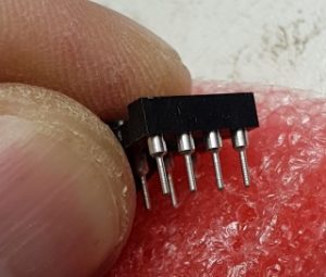
    The new BS170 in its socket
    The new BS170 in its socket

    After the weather zapped the output transistor (a BS150 FET) of my Ultimate3S beacon from QRP-Labs yet again, I was forced to replace the device, again. It is not a difficult job at all, just a little chore. This time I decided to make it easier on myself. Instead of replacing the transistor by soldering it in, I decided to use a plug-in base so that I can just whip it out and plug in a new one.


    The bad guy
    The bad guy

    The offending object is shown clearly out of focus, just to gain some perspective. I always solder mine in with at least 5mm long legs sticking out above the PC Board to allow for fitting a heat sink.


    Decapitated
    Decapitated

    Decapitate the weakling in one go! Don’t waste time, just stick in the cutter and cut out the weakling, but do it as far away from the PCB as possible, leaving the stumps for later removal. I placed a small piece of paper behind the legs to make it easier to see in the picture.

    Now you can just heat the legs one-by-one and tap the board so the legs will drop out. Easy.


    IC Sockets
    IC Sockets

    Next, consult your trusty junk box or buy some of these IC sockets. They can be any number of pins from 8 to 28, it doesn’t matter. I just happened to have 8-pin variants in stock. Avoid the cheap ones with the single flat blades that pushes to one side of the IC only.


    Cylindrical pins
    Cylindrical pins

    This is what you want. These cylindrical (or tubular) legs will make good contact with the FET’s legs and they are tapered and coated so your connection is guaranteed to be solid.


    Three Pins
    Three Pins

    Solder three pillars into the three required holes. I managed to keep the front two pillars together and the back pillar is separate due to space constraints. You might even put a drop of glue to hold everything together, but that isn’t necessary and I didn’t do it.


    In Place
    In Place

    Cut the FET legs a little bit shorter, but not too short, and plug it into the sockets. Make sure it goes down all the way and is oriented correctly.


    You can see a close-up view of FET in position at the start of this article.

    Completed
    Completed

    Admire your work upside-down and from the side, making sure everything fits correctly.

    Put back your heat sink, close the covers and away you go!

    Next time, replacing the BS170 will be a cinch.

  • Making (Big) Waves

    Yaesu FL-2100Z
    Yaesu FL-2100Z

    The Yaesu FL-2100Z is a classic HF amplifier. It sits near the end of a long life line of multiple variations and models of the basic 811A or 572B triode valve, all using exactly the same grounded-grid core design, and all of them making nice big waves in the ether when fired up.

    I was lucky enough to lay my hands on three of them over time. The first one came to me from an estate in Durban, KZN, in perfect working condition I might add, and I was stupid enough to sell it to a fellow ham that pleaded poverty. He still owes me money after selling it onwards immediately at a profit. The last two came my way in more fortuitous ways and have been a pleasure to own and I’ve made big waves with them while they were visiting my shack.

    The one was nearly in original (i.e. unmodified) condition, the other lacked the row of input filters in the back. The one had 572B lamps whereas the other was retro-fitted with 811A lamps. Both were sort-of working but not really, and over many evenings I painstakingly studied the details of what was working and what was failing. It was great to have two examples with two different faults, because I could compare faults and figure out their individual problems.

    Just remember, I have never worked with valves before. I don’t know them, I don’t like the seriously high voltages around them, nor the heat, and just to add injury to insult I once forgot to disable the HV interlock switch sending me running for cover as the whole thing exploded with loud noises and blown fuses. These things are like hot women: Pretty to look at but you will get burnt if you touch them.

    But we made peace and progress more or less at the same time and eventually both are working. My feeling is that the circuits are relatively simple and the resulting box robust. Once you have twiddled all the knobs and read all the meters, they actually produce some nice power and can make nice big HF waves. For example, with an input of 25 watts the 572B valves (after tweaking for optimum output) spat out a good 500 watts key-down on 40m where I like to operate. The 811A valves were also willing but maybe a tad less capable at 450 watts. I must add that the 572B’s were eager to give a little more with a little more drive, whereas the 811A’s needed a slightly bigger push to give out more. Both worked very well though.

    I uploaded a short video of the testing of the first one to go live at YouTube Video Link showing how easily it puts out 500W key-down even in a somewhat mis-matched feed with high SWR. It is shaking that wire mercilessly by the tail!

    Sadly I have to let them both go. I started another project to build a solid-state amplifier in the same output range, the so-called DN-600, and there isn’t enough rack space in the shack for all of them. The Yaesu FC-902 tuner stays, though, as it has proven to be both accurate and useful. I compared the power it measures on its built-in meter with an expensive scope-voltmeter into a dummy load and I’m satisfied that it tells the truth. Plus my only antenna that can handle that sort of power is my (unmodified) G5RV which, as you know, needs a little impedance matching. Having said that, when I use the G5RV for WSPR (QRP 200mW) I consistently get very good spots, so please don’t come tell me it is rubbish and you lose power when you use a tuner – my experience is exactly the opposite.

    I will be remiss if I don’t mention the three gentlemen who assisted me in this project. Firstly Jacques Scholtz ZS6JPS who introduced me to the AWA (Antique Wireless Association) and was always willing to give advice. Secondly Renato Bordin ZS6REN who kindly donated a secondhand 811A which came in very handy, thank you. Finally Adi Loupo ZS6CNC for setting up the valve tester and helping me test all my motley collection of good and bad lamps, and helping me to get two pairs or lamps that worked together. Thank you guys, you were demonstrating the true amateur radio spirit.

    I’ll publish some more details and photos of the work I did in the next few days, I just wanted the word to get out so long. Here is one last photo of the pair of 811A’s to close off with:

    811A's Working Full Steam
    811A’s Working Full Steam
  • Sizing of a Solar Charging System for a QRP Beacon

    When you run a small low power beacon like the
    Ultimate3S from QRP-Labs it is attractive to consider
    powering it from batteries with a solar panel.
    But how long will it last?

    A number of things are conspiring to make our lives as amateur radio experimenters difficult. On the one hand the cheap Chinese imports make it very easy to add small but useful gadgets to your shack. On the other hand technology itself is rapidly moving towards smaller and less power-hungry devices causing your stuff to e outdated two days after you buy it!
    At the confluence of these two streams sits low power beacons: Small devices that can send out a radio signal and only sniffs at the fuel tank. The latest amateur party balloon experiments are a case in point: With a total payload measured in grammes they circumnavigate the world several times over.
    But what about the more common homebuilt beacons? Let us take for example the Ultimate3S beacon kit that was constructed by several South African amateurs: Can this beacon be powered from a solar panel? Let us investigate further.

    How deep is your pocket?
    The first and most important factor to take into account is that almost nothing is impossible if you spend enough money. You can buy incredibly efficient systems with enormous battery capacities at a price that will bring tears to your bank manager’s eyes.
    I don’t operate at those altitudes, my oxygen supply will be cut off very quickly by my Minister of Home Affairs. I’m going to limit my spending to items that the average hobbyist can afford.
    Thus, it is spoken, that we will be limiting the most expensive part of the discussion – the batteries – to standard 12 volt 7 amp-hour (gelcel) batteries. I want to do this because my experience is that the batteries are the items that require the most money and the most maintenance. This might not produce the most optimized technical design, but it will certainly optimise my chances of survival when I get home.

    However, for the technically inclined I have a challenge near the end of this article – please participate!

    How much is enough?
    In order for you to size your solar system for your beacon correctly, you need to note the power rating of the beacon and all its support components that will be drawing power from the system.
    For example, let us take the popular QRP-Labs Ultimate3S beacon to see how one might calculate the correct size of the solar system. This example system is configured with:
    • no receiver slots and no 3G or network connection
    • a standard GPS for timekeeping
    • no relays for band-hopping
    • a standard Si3531A frequency synthesizer
    Measuring the beacon together with the GPS it draws around 150mA from the 5v supply in receive mode (standby as some would call it). During transmit it jumps to 350mA or more. However we are only transmitting for small periods at a time and let’s say we are running WSPR with one transmission every 20 minutes, i.e. 2 minutes out of every 20 minutes or around 10% of the time.
    This is easily calculated to be:
    • In Standby mode about 2 Watt for about 90% of the time; and
    • In Transmit mode about 4.7 Watt for about 10% of the time.
    Without being too scientific we can estimate an average consumption of about 200mA .
    Now a very basic assumption is that I want to operate around the clock 24×7 and thus:
    TOTAL WATTS = 12 VOLTS X 0.2 AMPS = 2.4 WATTS, X 24 HOURS = 57.6 WATT-HOURS PER DAY.
    Before you kill me for using the wrong numbers, remember I am drawing current from a 12v battery through a linear regulator (LM7805), thus 12v x .2A = 2.4W. We can easily round this up to 60 watt-hours per day.

    If you fitted the OCXO (Oven-Controlled-Crystal-Oscillator) to gain better frequency stability you must add at least 200mA to that number, which doubles your demand. Quite frankly I would not recommend that for a solar powered system.

    Sizing of the Inverter / Converter / Regulator
    Reducing the 12 volt battery line to the 5 volt line required by the beacon, we often take the easy way out with a small 3-pin linear regulator a la LM7805.
    The more modern solution might be to use a switching inverter or regulator (12V → 5V or 3.7V → 5V), but that comes accompanied by its own set of negative attributes such as noise which cannot simply be ignored.
    Assuming your peak power drawn is only 350mA during transmit, your inverter / converter / regulator needs to be able to deliver this power without overheating. This translates loosely to heat in the quantum of:
    7V X .35A = 2.45 WATT!
    Yes, a heatsink is recommended.
    Note: The inverter/converter must always be bigger than the maximum peak power demand.

    Sizing of the solar PV array (solar panels)
    For the beacon alone, excluding other losses, we will use approximately 57.6 Watt-hours per day. We need to generate more energy than we use to stay ahead of a flat battery, so …
    The charging hours effectively available per day can vary between 4.5 hours (Cape Town) and 6 hours (Polokwane) per day and let us therefore use 5 hours as a good estimating number.
    If we increase the 57.6 Watt-hours per day to say 100 Watt-hours (to allow for some extra charging when really-really needed), the amount of panels we will need is:
    100 WATT-HOURS / 5 HOURS = 20 WATT
    So the minimum panel size we need is a 20 Watter at 12 volts. More thoughts about the voltage later.

    Rating of the Batteries
    Normally it is preferable to design a solar system for higher voltages because that reduces the cable and system losses which could be as much as 15% more in a 12V system. However in this case a 12 V configuration should be fine.

    Also remember that we also do not want to cycle our batteries more than 50% deep, or even less if we can. To be honest, these cheap 12V/7Ah batteries shouldn’t be discharged to less than 80% of their rated capacity otherwise their lifetime is drastically reduced.
    If we agree to 50%, the batteries that we need must be in excess of 100 Watt-hour x 2. (times 2, to reduce the battery cycle to 50%). For 80% we need five times the rated capacity!
    So we need at least a 200 Watt-hour battery bank. This is the smallest bank of batteries you can go for in this application. You also know the average use is about 100 Watt-hour per day, so if you want additional capacity – say for a rainy day – you need an additional 100 Watt-hour of battery bank.
    But let us not digress. Let us get back to 1 day capacity. For our 12V system we need
    100 WATT-HOUR / 12V = 8.33 AMP-HOUR

    That is much more that the capacity of one battery. If we use standard 7 Amp-hour batteries, that would mean two batteries. Anything less could leave you powerless on a cloudy day.
    In fact, we could digress here into a discussion of two batteries in parallel, or two in series (24V) but sufficient to say that the 24V option is likely to be a more efficient approach.
    Also remember that if you change anything in the configuration, for example add additional bands, you must reconsider the above calculations.

    Rating of the Regulator (MPPT)
    A MPPT, or maximum power point tracker is an electronic DC to DC converter that optimizes the match between the solar array (PV panels), and the battery bank(s). They have become very popular lately, due largely to their ability to protect and extend battery life while transferring maximum energy.
    The MPPT solar regulator is designed according to the output current rating to the battery, in other words it is aligned to the battery characteristics. Don’t buy a lighter version thinking you are going to use less.

    We know we have 20W of panels (independent of the configuration). If we choose a 24V battery bank then 200W/24V = 8.3A MPPT. If we choose a 12V system, this would regulate 200W/12 = 16.6A MPPT. This may yet be another reason why you would want to consider a 24V (two batteries in series) system.

    The Complete Solar Power System
    From the previous assumptions and subsequent calculations, this is an example of a practical system:
    • 1 x 12 V to 5 V step-down regulator at 1 A
    • 1 x 20 W Solar Panels at 12 V
    • 2 x 12 V / 7 Amp-hour batteries
    • 1 x 16A MMPT Regulator
    Be aware that this is only a guideline and your mileage may vary. For example if you are not too concerned with battery life, you could quite happily operate with one battery.

    Gotcha’s
    The above discussion is very generic and there are many things that can go wrong or can go right, depending.
    The battery should be protected from discharging too deeply, but at the same time the beacon must be protected from the power cycling up-and-down too often. It could freeze upon startup.
    Any switching power supply will influence the quality of the signal and may even prevent the beacon from being spotted completely if not sufficiently dampened.
    The LCD display can be switched off completely to save a few milliamps and thereby reducing power demands.
    Adding bandhopping, more bands or more frequent transmissions may severely reduce battery life as calculated above.

    The Real Challenge
    I mentioned earlier that I have a challenge for the more technically inclined amateurs.
    It is my considered opinion that the system we discussed above doesn’t make very good use of all the resources we have at our disposal. I’m convinced that some optimisation isn’t only possible, but also easy to achieve.

    For example, I’m wondering if the latest lithium batteries running 3.6 V or 7.2 V or even 11.2 V (as used in model aeroplanes) isn’t going to be a much better reservoir.
    I’m also wondering if the up-and-down of voltages, from the solar panel to the battery to the beacon, cannot be done in fewer steps, or even eliminated completely?
    So here’s the challenge: Please send me your ideas (including eBay links if possible) for a better and more efficient system. The best design will be featured in the next issue of RadioZS.

    Until next time,

    73s de ZR6LU Leon Uys from Johannesburg 0825735580

  • Measuring the QRPp’s Isn’t Easy

    SWR Detectors
    SWR Detectors

    Interesting how a development in one area of this hobby can force a sudden change of direction to explore some new areas. I’ve been happily experimenting with my Hans Summers Ultimate 3S kit when I realised that I could band-hop and get a picture of propagation conditions updated every 30 minutes or so. Cool idea.

    But band-hopping requires a multiband antenna. Alternatively a tuner or something to adjust the U3S (which has quite a robust albeit low power output) to the piece of wet string hanging out the window. Even then, one may never know exactly how well you are getting out, and therefore whether your propagation forecast is accurate.

    Thus the sudden change in direction: I want to measure exactly how much RF is going down the cable to the antenna. This should be easy, right? A quick search on Google brings up dozens of very good kits and circuits, and I dive headlong into the challenge. That was a few weeks ago already. And I learnt a painful lesson: There are not a lot of options available for the QRPp operator.

    Let me be honest, many of the circuits and kits I saw were designed for the American market where they must handle kilowatts with a minimum scale of 100 watts. But when you start talking in the milliwatt region there is a big void. I spent hours and hours winding toroids, soldering up detector boards, wasting tons of paper taking meticulous readings, all in the 5 watts plus region. But I couldn’t get things to work in the 150mW and less region where the Ultimate 3S is working.

    So here is the challenge: Does anybody have a working circuit or plan for a QRPp SWR / Power meter? Drop me an email and I can share some of the ideas I have already tried, but I’m desperate for some new ideas.

    73s de Leon ZR6LU from Johannesburg 0825735580
  • Ultimate 3 S – part 1

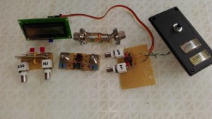
    Ultimate 3 S
    Ultimate 3 S

    My latest baby! I will write the full story in a few installments, from the back to the front so to speak, in other words I’ll show you the final result first before going back and showing pictures of the construction and so on.

    Of course I’m talking about my Hans Summers Ultimate 3S beacon transmitter.

    She came to me via the UK, where Ken Murdoch put it into his luggage and transported it to me in the far south over the December 2015 holiday period. Thus we avoided any issues with the South African Post Office who is notorious for “losing” packages.

    After some construction time, not a lot I might add, she lit up her lights and started WSPR-ing sweet tones to the world. ZS6USA was the first to respond.

    It is possibly the best kit I’ve ever built and the sweetest performer I can remember.

    Watch out for part two.

  • WSPRing is addictive

    WSPR on 2m
    WSPR on 2m
    Like the mermaid calling the sailor, this mode called WSPR seems to be calling me back every time. Circumstances pushed me out of the house into my new outside semi-underground shack which made me QRT for a while while I was painting and renovating, but the first thing I did (after making the few compulsary voice contacts on 40m) was to set up my WSPR station again.

    But this time it came with a different urgency. After getting the basics right and decoding a few stations on 10m (wow the bands are lively!) I tried 6m. My antenna isn’t very good but what the heck the Flex-1500 can go there. No decodes. Can it go higher? Nope, that is the highest frequency the Flex will do.

    Thus out comes the old trusty Yaesu FT-857D, still a remarkable and reliable radio after so many years, a true benchmark model to compare against. The G4ZLP modem is also the best money I ever spent for first-time-lucky set-ups. But oh dear, nobody on 6m (lots on 10m), so we tune up to 2 meters on a nice vertical. Still no decides, sigh. After reading a bit more, it seems like not a lot of people are WSPRing on 2m and so I posted in the SARL forum as well for some help. Tropo ducting is rife at the coast and my always-opportunistic self decides to make 2m a priority.

    As of this morning my station is QRV on 144.489MHz (dial setting) and I’m in and out of the shack doing chores while thinking about the next step. I’m going to have to wake-up shake-up some rusty old hams to participate otherwise I’ll get no spots. I’ll keep you posted.

    P.S. the upshot of this all is that I spoke to the minister of home affairs about how far we can bend the budget and she agreed that we have enough to buy one of Hans Summers’ Ultimate U3S QRP kits. I’m so excited I can eat raw popcorn!

  • Flex-1500 – Starting the SDR journey

    Flex-1500 SDR
    Flex-1500 SDR
    I might be older, but I’m very young at heart when it comes to technology. I love playing with all the latest gadgets and adopting my hobby to the emerging technologies. One example would be that I only run solid-state amplifiers (watch out for my series of articles on building my own). I also talk WSPR and digital modes fluently.

    So it would come as no surprise that I tested one of the RTL-2832 USB adapters to see what I could see. And I saw the incredible power of the panadapter display and waterfall combined, and I started thinking. I had to think, because my Minister-Of-Home-Affairs is always asking me why I need another radio since I can only talk on one radio at one time. Doesn’t she understand boys and their toys? Anyhow, I started realising that there are many options out there – most completely out of my range. Sigh.

    Thus, when Hans ZS6KR placed an ad on the swopshop for a second-user Flex-1500 I called immediately and snared myself one of these beauties. I’ve owned it for less than 24 hours, yet it has charmed me in more ways than I can imagine. The receiver (and I mean right up to the display) is incredible. And the 5 watts is a non-issue because my HLA-300V took to the radio like a duck to water, putting out a nice 50-80 watts into the antenna wires.

    I cannot predict where this love-journey will end. All I know is that suddenly a whole new world was opened to me. Yes, it might be the entry-level SDR receiver and already four or five years old, but it has everything necessary to keep me feeling warm and fuzzy during the upcoming winter months.

    I’ll keep you posted. 73s.

  • Nixie Tube Clock

    Nixie Tube Clock
    Nixie Tube Clock

    I’m sorry in advance if I’m going to hurt somebody’s feelings here, but you cannot be a radio ham if you not like small glass bottles that glows in the dark. Even if you are a die-hard solid-state amateur like me, you absolutely HAVE-to-have something that indicates or flashes or twinkles in your shack.

    I managed for a while, but then the nixie tube gogga bit me. And the more I read about it, and saw the videos, the more I lusted. Unfortunately, the poor-gogga bit first and my empty wallet reminded me that my lust was higher than my bank account. Of course, I tried importing. It just adds to your misery because sending parcels via the Post Office has become a futile attempt.

    Then my new best friend GumTree knocked on my door. I found Raymond in Bedford View who makes beautiful nixie clocks. When you look at his website, you can believe me that the clocks are even prettier in real life. He has already optimised his design to include a FM Radio and it all hangs together very well. Go get his website for more information.

    So now in the evenings I sit in my shack and admire my newfound Nixie Tube Clock.

  • QRSS on 30m with Arduino

    QRSS on Arduino
    QRSS on Arduino
    QRSS is not something I knew anything about, until I stumbled across a useful use for my Arduino: A small daughter board (called a shield) with a few components to turn it into a QRSS transmitter.

    I admit I am lazy and morse code is way out of my reach – know the joke? did it once and didn’t like it? Similarly I had never heard a QRSS signal until I built and tested my module. But once it was up and running I started to become a little more interested in trying to decipher the morse code. And once that got going, I couldn’t help but try to listen out for other QRSS callsigns.

    There is a lot of information on QRSS on the internet, so I will only comment on my own experiences. Firstly, the kit was easy to build.

  • Mobile in Hibberdene KF59gk

    Hibberdene KF59gk 11 Oct 2014a
    Hibberdene KF59gk 11 Oct 2014a
    I had the privilege to go on holiday for a few days to the coast, staying in a lovely woodenframe cottage with my dogs for 4 days. My wife allowed me to pack a small radio, and so on the Saturday I managed to catch a few contacts with my new/old (that’s another story!) IC-703, from the balcony of the cottage overlooking the Indian Ocean in Hibberdene Grid Square KF59gk, kindly rented from Walter and Louise, Hibberdene Escape. They come highly recommended.

    Initially I called ZS5GS and Gerald came booking back 59+ and gave me a 55, with which I was very happy because I was using a short ICOM AH-703 antenna, a portable multibander with a total length of 1.4 meters (4.6 ft)! Incredible performance for such a small device. I also had a similar report back from Johan ZS6AF.

    Thanks guys, you made my day! 73s.