Interesting how a development in one area of this hobby can force a sudden change of direction to explore some new areas. I’ve been happily experimenting with my Hans Summers Ultimate 3S kit when I realised that I could band-hop and get a picture of propagation conditions updated every 30 minutes or so. Cool idea.
But band-hopping requires a multiband antenna. Alternatively a tuner or something to adjust the U3S (which has quite a robust albeit low power output) to the piece of wet string hanging out the window. Even then, one may never know exactly how well you are getting out, and therefore whether your propagation forecast is accurate.
Thus the sudden change in direction: I want to measure exactly how much RF is going down the cable to the antenna. This should be easy, right? A quick search on Google brings up dozens of very good kits and circuits, and I dive headlong into the challenge. That was a few weeks ago already. And I learnt a painful lesson: There are not a lot of options available for the QRPp operator.
Let me be honest, many of the circuits and kits I saw were designed for the American market where they must handle kilowatts with a minimum scale of 100 watts. But when you start talking in the milliwatt region there is a big void. I spent hours and hours winding toroids, soldering up detector boards, wasting tons of paper taking meticulous readings, all in the 5 watts plus region. But I couldn’t get things to work in the 150mW and less region where the Ultimate 3S is working.
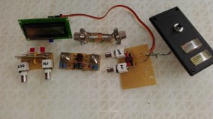
So here is the challenge: Does anybody have a working circuit or plan for a QRPp SWR / Power meter? Drop me an email and I can share some of the ideas I have already tried, but I’m desperate for some new ideas.
Tarheel Antenna ControllerI have lately been taking some family holidays at the coast and this presented me with the ideal opportunity to play with portable and/or mobile antennas.
Initially I used a standard 108″ whip antenna, tuned with a tuner. I bolted it to my towbar with a custom bracket. It kind-of works but deep inside I had the feeling I should try something else.
Then I played with an Alpha Moto Mobile Antenna (all-bander) that I purchased from Ivan Marks in Cape Town, together with a Alpha Stainless Steel Quick Release Jaw Clamp Mount. The jaw clamp is awesome and will stay in my toolbox. The antenna worked well from 20/15/10 but it was – as can be expected – a few points down on 40m. Interesting antenna though.
But eventually I scraped together enough money to lay out for a Little Tarheel II from Sams Radio Accessories. It was both very expensive, and a complete and utter technical surprise at the same time. While I still think I paid far too much for a simple antenna (cough-cough), it is the design and installation that is most intriguing.
Firstly, I was wrong. I did not understand how a screwdriver antenna works, and I’m not talking about the engineering. I nearly added another G to the purchase to buy a controller. Boy, was I lucky that the item wasn’t in stock! See, the issue is that the Tarheel doesn’t need a tuner – it is for all practical purposes a tuner in itself. Nobody tells you that when they talk about the antenna.
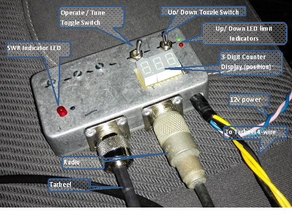
What is very useful though is a watt-meter or a SWR-meter, and maybe a turns-counter. So after using the antenna for a few days I started checking the possibilities and I built a prototype of a combination box with:
Up / Down switch (to replace the factory-supplied one)
SWR Bridge / meter / indicator
Counter (counts how much of the coil sticks out)
It is working very well and I will make more details available as I find time to make drawings and test and improve the design.
Hibberdene KF59gk 11 Oct 2014aI had the privilege to go on holiday for a few days to the coast, staying in a lovely woodenframe cottage with my dogs for 4 days. My wife allowed me to pack a small radio, and so on the Saturday I managed to catch a few contacts with my new/old (that’s another story!) IC-703, from the balcony of the cottage overlooking the Indian Ocean in Hibberdene Grid Square KF59gk, kindly rented from Walter and Louise, Hibberdene Escape. They come highly recommended.
Initially I called ZS5GS and Gerald came booking back 59+ and gave me a 55, with which I was very happy because I was using a short ICOM AH-703 antenna, a portable multibander with a total length of 1.4 meters (4.6 ft)! Incredible performance for such a small device. I also had a similar report back from Johan ZS6AF.
Wouxun KG-UV920PI must be more careful, Sam does it again! So I walk into Radio Accesories innocently, just wanting to say Hi to Sam and Bertrand and check up on things. For some reason the conversation drifts to the new special that he is running for the new hams that just passed their RAE exams – a Wouxun KG-UV920P VHF/UHF 50watt for a very good price.
Somewhere during the conversation Sam lets me hold the radio in my hands, and as you all know, one you have touched the goodies your hands are stuck with superglue and you can’t let go.
Eventually I walk away with the Wouxun KG-UV920P radio (the latest version I believe), a Surmen NR-770R dual-band antenna, a K412 lip-mount bracket, and a Surmen SC-ECH 5 meter RG58 body mount harness – the complete outfit. I opted for the better bracket because it allows 3D adjustment and the slightly better gain antenna because the cost difference wasn’t big, but if you are tight on the cost then you can buy the slightly cheaper versions – I’m sure Sam will be happy to supply.
Rushing home (it was after 5pm) I unpacked everything on the front seat of the car expecting a major installation effort. I was pleasantly surprised to find that all the screws, clips and tools were included. Installation took me the full amount of 20 minutes. All-in-all this is a very good combination with everything included – just add 12 volt and go! My first QSO was through a repeater and good signal reports followed effortlessly.
My subjective review of the radio is that it has a very good receiver. It feels like the receiver is super-hot, picking up signals and holding them when driving. I like it and can recommend this as a good buy for an amateur looking for a FM rig.
Are you like me and most other Hams, where your needs far exceed your budget? Where your have-to-haves stretches far further than your pocket money? And on top of that, if you are inquisitive and like experimenting like I do, the shortage of money really hurts.
Now please understand what I am saying: I have a good solid radio with a fantastic antenna that works very well and gives me great pleasure. When I operate. Which is quite often. Nope. What drives me is this insatiable curiosity to know how things work, and to try to replicate the mechanisms until I understand them. The “second” radio projects. I’m not touching my main radio, no, but my second radio is used for all sorts of experiments. My second radio is often lying in pieces on the operating table with all sorts of measuring tools sticking out of it.
Thus the story starts with me looking for a new vertical antenna. The piggy bank is standing on zero, and the desire is standing at boiling point. Nothing that is advertised seems to come close to my budget. What is a man to do? However, the Comet CHA-250BXII that is advertised for around R4995 seems interesting from a variety of points:
It is a multibander. Essential for me.
It seems to be a clean design with no coils and traps. I like that.
It can be assembled in minutes
They say it doesn’t need radials. We will see.
It stands only 7 meters tall. Ehh, what did you say?
Reviews vary from good to bad. Most people think it is a good listening antenna but not a good transmitting antenna on the lower bands. The really attractive thing is the easy installation. It consists of a 7 meter high radiator, with a tin can at the bottom that holds whatever black magic it does. Looking further it appears that Iain Crawford VK5ZD had some trouble with his Comet CHA250 (the link has lots of pictures and information). Great article. Apparently he got some water in his tin can, so he decided to open it and see whats inside. My kind of man!
And once the can of worms have been opened, the design seems to be fairly simple 6:1 transformer feeding a NON_resonant element. Searching around I could find any number of people that have tried to build a similar vertical antenna. One of the best is Broadband Vertical [click here] by Martin Ehrenfried G8JNJ where he writes about his experiments with a CHA-250 style vertical. He compares various commercial verticals. His measurements indicate that no tuner is required for this CHA250-style antenna (just like the commercial version) and that it only needs a RF transformer. He follows that with a second article where he improves the design significantly – a must-read.
Look, this small little 7 meter high baby antenna is not going to perform like a huge tri-bander on a tower 40 meters above the ground. This is to be expected. But it works good enough and is very easy to construct. So I set out to make one from parts I have lying around. You can follow the slide show on my RigPics page. Firstly I decided to use 4x RFI Snap-On Chokes from MFJ that was intended to be used as RG-213 coax shields. They have inners around 10mm, and thus a few centimeters of 10mm copper gas pipe was scrounged. Cut the two copper pipes to stick out 2mm on both ends. For the inner cable I wanted a high voltage insulation, so I stripped the black PVC from a few centimeters of an electric fence high voltage feeder cable. This was fed through the two copper tubes. The one side only has two windings, the other 4 windings. The hardest part was soldering a piece of 1.5mmsq wire onto the copper tubes (they conduct heat very quickly away from the joints). Finally I connected it all up to a piece of 7 meter long electrical wire thrown up into a tree.
The SWR readings were reasonable and I could hear stations all over the band. As expected, on the lower bands the remote stations gave me lower S-readings although I could hear them well. This is exactly what Martin predicted.
7.060MHz 1.4
14.250MHz 1.1
21.250MHz 1.3
28.850MHz 1.5
This is an excellent constructional antenna, supported by lots of information on the internet. The fact that it tunes across all the ham bands without a tuner is a big plus for me. It is a good listener. The only downside is that it is not a particularly good transmitter on 80 and is marginal on 40. It is definitely in my backpack for my next weekend away. Enjoy the slides on my “RigPics” page.
Antenna SprayThe ultimate solution to HIGH SWR! Just use a can of this spray and all your problems will disappear!
I couldn’t help but smile and re-post this picture. I have no idea who the original author is, and I will fully acknowledge him/her if they let me know. I saw the picture for the first time on facebook on the page of David Lowe.
Just proves we are not a bunch of boring old timers, we do have a sense of humour!
My back wallWell, I had to do this: Take a picture of my back wall, to explain how bad my QTH is located. In this view I am looking at the back walls of my neighbours 2 or 3 houses up. The river is on the right, and the power line on my left. The red arrow is where I will be standing for my next photo. River ViewIn the next photo I walked out my back yard towards the river, I turned around, and this is what I can see.
I am standing under a 88kV line, I can see the second line in the left of this picture, and I can barely make out my DSTV dish and the silver of my 2m CP22E antenna. All my antennas are just about halfway up the trees and a third up on the towers.
I have no chance to get a signal out, especially in summer when the trees have leaves.
To add to my frustration I am at the lowest point in the area. The municipal storm water drains are next to my erf, and my altitude is around xxxx MASL. Compare that to Sandton City, about 2km away as the crow flies, which is at xxxx MASL.
Vertical CP22E 2mSo, another sprout is springing up! This latest picture taken late on Friday afternoon, minutes after installation, shows my somewhat unsuccessful attempt to work VHF/UHF from my QTH. It is a 2m vertical (Diamond CP22E) that has 2 x 5/8 elements on top of each other. It claims a gain of 6.5dB and I must admit the build quality is very good. All the bits were in the box, so to speak, and it took me less than 30 minutes to mount.
The rest of the picture of the chimney shows my 2 SAT TV dishes, high up is the BroadGun Travelling Wave wire dipole, below that is the G5RV, and the 83m loop also passes through the view somewhere.
The BroadGun Travelling Wave wire dipole gives good results from 80m-10m at 100 watts and is almost permanently connected to my FT-840 for digital work. Depending on some random factors the loop gives slightly better results but not often.
The G5RV (in spite of the fact that it is standard and hasn’t been upgraded to the ZS6BKW specs) works extremely well. If I pull it up a little higher, or drop it a little lower, it just goes deaf! Exactly why I don’t know, but in this position it works very well and on voice I’m sometimes pumping a few extra watts through it – no problem.
The 83m horizontal loop is just strung from the trees and is interesting, it resonates on almost anything down to 6m. It is quieter that the G5RV and occasionally it is easier to work with.
But yes, the 2m vertical still doesn’t work. Connected to 15m of RG213 and mounted as high as it is I can just, but just, trigger the nearest repeater (Sandton). Simplex is just not possible as I am in a deep hole here and my signal just wafts over everybody’s heads (or antennas to be precise).
TopTV DishPicture of Thulani on the roof again. Useful to have a spannerboy when things drop to the ground. Anyways, to his left (picture right) is my newly installed, rusted and bent, 90cm dish pointing to SES-5 (also known as the TopTV satellite).
What a mission to get it going! No, not the holes in the chimney – Thulani took care of that. Not the 5th cable into the ceiling either. No, the frustration to get the dish aligned. I align my caravan-portable 35cm dish to DSTV in seconds, I’ve done it successfully many times over. I’ll write more about it in a follow-up, but here are some gentle pointers for TopTV (pun intended):
(1) The signal peak is going to be much sharper thank you think, and much sharper than DSTV. Yup, a single bump on the side of the dish will go from full signal lock to pie-in-the-sky nothingness. Make very small adjustments to the dish, otherwise you will miss it. DSTV is broad, man.
(2) The direction (azimuth) is slightly more to my left (from behind the dish; west) than what I though. I spent many hours with Google Earth and other spotter websites to get the exact direction, but they were slightly wrong by about 4 degrees or so. It might be the way my house lies on the stand, I don’t know. But keep on sweeping and you will find it. Elevation in my case was slightly more critical than azimuth.
(3) Make sure your LNB is 10700 or 10600 and set your alignment tool and decoder to that. It doesn’t work otherwise.
(4) The dish is going to point *MUCH* higher than you think is possible, and much higher than DSTV. I must have spent an hour on the roof pushing the poor dish completely out of shape getting nothing, nada, nilsch. Then I looked at the mounting bracket and it had an adjustment hole for higher elevations. First sweep and I had signal lock. It looks far too high on the photo but it works very well.
(5) Remember to turn your LNB to the new rotation, I left mine at 7 o’clock for SES-5 and it gives good results. DSTV is at 4 o’clock.
(6) A proper tool is worth every penny. Buy one, borrow one, whatever. You are NOT going to get it aligned without a proper meter. See 7 below.
(7) With DSTV the 22KHz signal is off and you can hear the buzzer quite loudly. That’s how the little DSTV buzzer works. It doesn’t work on other satellites or on TopTV. Nope, I tried it, don’t bother. Besides, the beam is so narrow you are unlikely to hear the blip anyway.
Having said all of that I am now the proud owner of two dishes watching TV on two monitors. Its going to give me a headache soon but it was fun while it lasted. My next venture is to watch some FTA (Free To Air) channels with my Strong FTA Decoder. If you have favourites – come-on … share please!
Magnetic LoopWell, if you have been following my other posts you will know that I live next to a monster of a power line servitude, less than 40 meters away from my shack. And 40 meters high. On my favourite HF band the noise levels almost hurt your ears. Something had to be done.
I tried a few things such as ferrite beads and a folded dipole but no real improvement. Scanning the internet the magnetic loop (small transmitting loop) antenna often came back as a lower-noise antenna, and after visiting Eddie (previous article) I decided to try my hand at building an experimental prototype. There was a lot of information available on the internet and I will add my plans and drawings to the bottom of the article as downloads. The achilles heel of these antennas is the high voltage capacitor, and after searching through two flea markets unsuccessfully I decided to make my own.
Essentially I wanted a copper water pipe loop that can be resonated around 7.060 MHz, as that would allow me to compare the results with my other radios and antennas. So I purchased a length of 28mm copper pipe and 8x 45 degree elbows. I also purchased a length of 50mm white PVC with which to hold the whole construction in an upright position. Initially I cut 7 pieces of 620mm each and soldered them together in a loose octagon with what seems to be a diameter in the 1550mm region. The 8th leg was to be decided later, and two loose pieces of around 200mm and 400mm respectively was soldered in temporily.
I need to say, right up front, that I am not a purist. While I will do strange and wonderful things to reach the optimum, my favourite motto is “MOL” (More Or Less). Get the basics right and the rest will take care of itself. So the few compromises I was willing to make are:
Not a round shape, but an octagon (8 sides)
A trombone capacitor
Feeding scheme to be decided later
Initially just to see if the loop will resonate at all I tried feeding it with a piece of circular coax in a faraday loop configuration but that didn’t really give strong results, but I think it was my own fault because I was standing too close to the loop. As soon as I soldered in a tab for a gamma match, things changed drastically.
First I tested with an old valve receiver spaced-plate capacitor (no power transmitting yet) and my antenna tester to see MOL (more or less) what frequency I’m getting. Wow, it was all over the show and I couldn’t get any useful readings. A cup of coffee and lots of staring into the distance later and I realised that the adjustments I’m making on the capacitor were WAY too much. In fact, lesson 1: To tune across the ENTIRE 40m band (100KHz) you only need from about 118pF to 121pF !! (yes, around 3Pf). Lesson learned: Make very small changes. Reference: LOOP CALCULATOR
After that it was plain sailing to the first QSO, I didn’t even bother to make proper solder connections for the gamma match and literally clamped a piece of 1.5mm electrical earth cable to where it resonated around a SWR of 1.5 and I fired up my set. Bingo, very nice contact with ZS6TY (Johan) and the concept is proven. At this stage, remember, I was using an in-line monoband trombone capacitor, and 1mm linear adjustment would give me a 25kHz shift in band so it was very sensitive, but it worked. In comparison to my G5RV when the noise was around S9 on the dipole, the loop would be S6 and the audio quality more or less the same. Definitely an improvement.
To see how I made the capacitor download the diagram at the bottom of the article.
Now for version 2 I wanted to make a remote-control capacitor. I don’t want to spend money on making it automatic yet, but I wanted to at least be able to change the capacitance from inside the shack. So out comes the soldering kit, out comes the two short pipes and they are replaced by two 300mm pieces. The old trombone capacitor is now turned through 90 degrees and the inside element is soldered to the one 300mm piece with a T-piece (look at the diagrams below). The outer element gets a 5mm brass nut soldered onto an end-cap with a 500mm long 5mm threaded link. A plastic coke bottle top becomes my adjuster on top and voila! the new antenna goes up.
In measuring I find the loop has a natural resonance at 24MHz (no additional capacitance inserted). As soon as the capacitor gets connected it can be tuned to 7.060MHz very easily, and the gamma match can be set equally easily. Unfortunately I offset the feed point a little to make room for the supporting pole, and I will have to go back and clean up the construction.
The next few weeks will be spent doing fine tuning and documenting the antenna. At the moment I’m pointing slightly west of north to get past the power pylon and hopefully catch some north-west ZS amateurs, but I was happily chatting to people north-east of me as well so I’m not too sure how deep the side lobe nulls are, yet. As it stands, it is a cloud warmer because I have no chance to get out horizontally or even at 60 degrees elevation.