Category: Repair & Restore

  • LED Lamp Behaviour

    LEDlamp
    LEDlamp

    So I got my hands on some of these 12 volt LED lamps (chips / modules / lights / whatever) and since I had enough to burn one or two “by accident” I thought I should spend a few minutes to get to know them better.

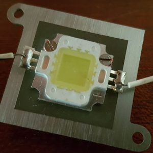
    I’m not referring to your regular little round 1.2 volt LEDs that we use by the millions for indicators and things on our projects, but instead the square, yellow modules around 25mm per side that makes white light for floodlights and so on.

    So before you pull out your 12 volt battery and blow up some lights, here is an important message: LEDs are current devices, they do not like constant voltages and will promptly reward you with a puff of smoke if you persist, much like the inkfish did in the sea when it tried to escape. You have been warned. Use a constant current to feed them and everyone will be happy.

    The other thing I completely underestimated is the amount of heat dissipated. They come without any protection whatsoever and your first job is to stick them to a heat sink. The 10 watt units I have require a heat sink not unlike the ones found in old computers.

    Once I had my head wrapped around this weird change from incandescent lamps, I had a lot of fun playing with my packet of LEDs. They produce good white light at reasonable powers, so even if you drop the current through a small resistor from a 12v car battery they will still work.

    However, there is one worrysome feature that I noticed. Assuming that each little LED is dropping around 2.98 volt (a not unreasonable number according to https://www.ledsupply.com/blog/wiring-leds-correctly-series-parallel-circuits-explained/) then you will end up with a matrix like this:

    LEDmatrix
    LEDmatrix

    or like this:

    A B C
    D E F
    G H I

    This is not the end of the world, except that if the LEDs are not closely matched they will draw different currents, with the weakest link obviously blowing first. I expect this will manifest as one LED lighting up slightly more than another in the chain.

    This is exactly what EDN found on their site at
    https://www.edn.com/design/led/4325905/Driving-high-power-LEDs-in-series-parallel-arrays


    I’ve made a short YouTube video to illustrate my concerns https://youtu.be/nf1654eiy1A

    Watch how the LED in position “C” lights up first and then goes on to illuminate brighter and brighter. It may be the one that burns out first, or overheats the most.

    What do you think, am I right or am I wrong?

  • Replacing the BS170 in an Ultimate3S Beacon

    The new BS170 in its socket
    The new BS170 in its socket

    After the weather zapped the output transistor (a BS150 FET) of my Ultimate3S beacon from QRP-Labs yet again, I was forced to replace the device, again. It is not a difficult job at all, just a little chore. This time I decided to make it easier on myself. Instead of replacing the transistor by soldering it in, I decided to use a plug-in base so that I can just whip it out and plug in a new one.


    The bad guy
    The bad guy

    The offending object is shown clearly out of focus, just to gain some perspective. I always solder mine in with at least 5mm long legs sticking out above the PC Board to allow for fitting a heat sink.


    Decapitated
    Decapitated

    Decapitate the weakling in one go! Don’t waste time, just stick in the cutter and cut out the weakling, but do it as far away from the PCB as possible, leaving the stumps for later removal. I placed a small piece of paper behind the legs to make it easier to see in the picture.

    Now you can just heat the legs one-by-one and tap the board so the legs will drop out. Easy.


    IC Sockets
    IC Sockets

    Next, consult your trusty junk box or buy some of these IC sockets. They can be any number of pins from 8 to 28, it doesn’t matter. I just happened to have 8-pin variants in stock. Avoid the cheap ones with the single flat blades that pushes to one side of the IC only.


    Cylindrical pins
    Cylindrical pins

    This is what you want. These cylindrical (or tubular) legs will make good contact with the FET’s legs and they are tapered and coated so your connection is guaranteed to be solid.


    Three Pins
    Three Pins

    Solder three pillars into the three required holes. I managed to keep the front two pillars together and the back pillar is separate due to space constraints. You might even put a drop of glue to hold everything together, but that isn’t necessary and I didn’t do it.


    In Place
    In Place

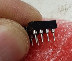
    Cut the FET legs a little bit shorter, but not too short, and plug it into the sockets. Make sure it goes down all the way and is oriented correctly.


    You can see a close-up view of FET in position at the start of this article.

    Completed
    Completed

    Admire your work upside-down and from the side, making sure everything fits correctly.

    Put back your heat sink, close the covers and away you go!

    Next time, replacing the BS170 will be a cinch.

  • Making (Big) Waves

    Yaesu FL-2100Z
    Yaesu FL-2100Z

    The Yaesu FL-2100Z is a classic HF amplifier. It sits near the end of a long life line of multiple variations and models of the basic 811A or 572B triode valve, all using exactly the same grounded-grid core design, and all of them making nice big waves in the ether when fired up.

    I was lucky enough to lay my hands on three of them over time. The first one came to me from an estate in Durban, KZN, in perfect working condition I might add, and I was stupid enough to sell it to a fellow ham that pleaded poverty. He still owes me money after selling it onwards immediately at a profit. The last two came my way in more fortuitous ways and have been a pleasure to own and I’ve made big waves with them while they were visiting my shack.

    The one was nearly in original (i.e. unmodified) condition, the other lacked the row of input filters in the back. The one had 572B lamps whereas the other was retro-fitted with 811A lamps. Both were sort-of working but not really, and over many evenings I painstakingly studied the details of what was working and what was failing. It was great to have two examples with two different faults, because I could compare faults and figure out their individual problems.

    Just remember, I have never worked with valves before. I don’t know them, I don’t like the seriously high voltages around them, nor the heat, and just to add injury to insult I once forgot to disable the HV interlock switch sending me running for cover as the whole thing exploded with loud noises and blown fuses. These things are like hot women: Pretty to look at but you will get burnt if you touch them.

    But we made peace and progress more or less at the same time and eventually both are working. My feeling is that the circuits are relatively simple and the resulting box robust. Once you have twiddled all the knobs and read all the meters, they actually produce some nice power and can make nice big HF waves. For example, with an input of 25 watts the 572B valves (after tweaking for optimum output) spat out a good 500 watts key-down on 40m where I like to operate. The 811A valves were also willing but maybe a tad less capable at 450 watts. I must add that the 572B’s were eager to give a little more with a little more drive, whereas the 811A’s needed a slightly bigger push to give out more. Both worked very well though.

    I uploaded a short video of the testing of the first one to go live at YouTube Video Link showing how easily it puts out 500W key-down even in a somewhat mis-matched feed with high SWR. It is shaking that wire mercilessly by the tail!

    Sadly I have to let them both go. I started another project to build a solid-state amplifier in the same output range, the so-called DN-600, and there isn’t enough rack space in the shack for all of them. The Yaesu FC-902 tuner stays, though, as it has proven to be both accurate and useful. I compared the power it measures on its built-in meter with an expensive scope-voltmeter into a dummy load and I’m satisfied that it tells the truth. Plus my only antenna that can handle that sort of power is my (unmodified) G5RV which, as you know, needs a little impedance matching. Having said that, when I use the G5RV for WSPR (QRP 200mW) I consistently get very good spots, so please don’t come tell me it is rubbish and you lose power when you use a tuner – my experience is exactly the opposite.

    I will be remiss if I don’t mention the three gentlemen who assisted me in this project. Firstly Jacques Scholtz ZS6JPS who introduced me to the AWA (Antique Wireless Association) and was always willing to give advice. Secondly Renato Bordin ZS6REN who kindly donated a secondhand 811A which came in very handy, thank you. Finally Adi Loupo ZS6CNC for setting up the valve tester and helping me test all my motley collection of good and bad lamps, and helping me to get two pairs or lamps that worked together. Thank you guys, you were demonstrating the true amateur radio spirit.

    I’ll publish some more details and photos of the work I did in the next few days, I just wanted the word to get out so long. Here is one last photo of the pair of 811A’s to close off with:

    811A's Working Full Steam
    811A’s Working Full Steam