Blog

  • My FT-840 is not resisting

    Yaesu FT-840
    Yaesu FT-840
    I am out on a limb here. Most of my friends use Kenwood or Icom radios but I love Yaesu radios, they talk to me (pun not intended)!

    It might have something to do with the fact that my first rig many years ago was a Yaesu FT-707 with tuner and PSU and everything and it served me well for many years. That is a story for another day. But back to the present: When I pulled my trusty 707 from the mothballs a few weeks ago the caps were obviously dry and the VFO danced a merry dance on the display, and fixing it was not going to be a quick-fix. So when I found that Charles King ZR5CTM had a secondhand Yaesu FT-840 he wanted to sell, the negotiations with the minister of finance started. What? she said – you already have so many radios (pointing to a broken 707). To cut a very long discussion short, I ended up making Charles an offer which was accepted and the parcel was posted to me.

    Disaster! The SA Post Office kept my precious parcel for 3 weeks, claiming there was a strike and that nobody was receiving any parcels. Yet on their track-and-trace, backed up by a phone call from the missorted post office branch, it clearly showed as having been sent to the wrong place twice. When I am calm again I will tell you that story of the strike that was not a strike.

    But back to the main story. Upon receiving my cargo it was obvious that it had seen a few hard bashes along the way and there was something loose on the inside. It powered on but didn’t transmit and a few other strange behaviours. Googling it pointed to a very common problem: There is a resistor R2213 near a voltage regulator that runs very hot and sometimes burns out. Well, I know Dion at LA Radio who fixes radios so off to the workshop we go. It seems that the ceramic part of the resistor can get brittle and in this case broke from the shaking around. It was a simple fix to attach a 10 ohm 10 watt resistor to the back of the chassis with two connecting wires, and voila! tha radio works like new. We chose not to drill any holes in the chassis because we didn’t want microscopic metal shavings to settle inside the radio. Have a look at our mod:

    R2213
    R2213

    The work we did is based on the article by John E DeBarr Jr aka November Alpha Eight Yankee [click here] but we had to use another component that is locally available. Instead of a 8.2 ohm or as some other websites say 9.1 ohm we only had a 10 ohm resistor available. It doesn’t seem to make any noticable difference. I took some pictures and can send you a PDF copy of my own work as we progressed but John’s article is quite clear with some very good instructions and pictures, for example this one shows the old resistor still in position (mine was broken):

    R2213 inside
    R2213 inside

    My 10 watt resistor hanging off the back of the radio gets very hot, so I can imagine what the original puny 3-watter must have felt like inside the radio. Definitely a recommended procedure to prevent further damage to the main PC Board.

  • My MagLoop so far

    Magnetic Loop
    Magnetic Loop
    Well, if you have been following my other posts you will know that I live next to a monster of a power line servitude, less than 40 meters away from my shack. And 40 meters high. On my favourite HF band the noise levels almost hurt your ears. Something had to be done.

    I tried a few things such as ferrite beads and a folded dipole but no real improvement. Scanning the internet the magnetic loop (small transmitting loop) antenna often came back as a lower-noise antenna, and after visiting Eddie (previous article) I decided to try my hand at building an experimental prototype. There was a lot of information available on the internet and I will add my plans and drawings to the bottom of the article as downloads. The achilles heel of these antennas is the high voltage capacitor, and after searching through two flea markets unsuccessfully I decided to make my own.

    Essentially I wanted a copper water pipe loop that can be resonated around 7.060 MHz, as that would allow me to compare the results with my other radios and antennas. So I purchased a length of 28mm copper pipe and 8x 45 degree elbows. I also purchased a length of 50mm white PVC with which to hold the whole construction in an upright position. Initially I cut 7 pieces of 620mm each and soldered them together in a loose octagon with what seems to be a diameter in the 1550mm region. The 8th leg was to be decided later, and two loose pieces of around 200mm and 400mm respectively was soldered in temporily.

    I need to say, right up front, that I am not a purist. While I will do strange and wonderful things to reach the optimum, my favourite motto is “MOL” (More Or Less). Get the basics right and the rest will take care of itself. So the few compromises I was willing to make are:

    • Not a round shape, but an octagon (8 sides)
    • A trombone capacitor
    • Feeding scheme to be decided later

    Initially just to see if the loop will resonate at all I tried feeding it with a piece of circular coax in a faraday loop configuration but that didn’t really give strong results, but I think it was my own fault because I was standing too close to the loop. As soon as I soldered in a tab for a gamma match, things changed drastically.

    First I tested with an old valve receiver spaced-plate capacitor (no power transmitting yet) and my antenna tester to see MOL (more or less) what frequency I’m getting. Wow, it was all over the show and I couldn’t get any useful readings. A cup of coffee and lots of staring into the distance later and I realised that the adjustments I’m making on the capacitor were WAY too much. In fact, lesson 1: To tune across the ENTIRE 40m band (100KHz) you only need from about 118pF to 121pF !! (yes, around 3Pf). Lesson learned: Make very small changes. Reference: LOOP CALCULATOR

    After that it was plain sailing to the first QSO, I didn’t even bother to make proper solder connections for the gamma match and literally clamped a piece of 1.5mm electrical earth cable to where it resonated around a SWR of 1.5 and I fired up my set. Bingo, very nice contact with ZS6TY (Johan) and the concept is proven. At this stage, remember, I was using an in-line monoband trombone capacitor, and 1mm linear adjustment would give me a 25kHz shift in band so it was very sensitive, but it worked. In comparison to my G5RV when the noise was around S9 on the dipole, the loop would be S6 and the audio quality more or less the same. Definitely an improvement.

    To see how I made the capacitor download the diagram at the bottom of the article.

    Now for version 2 I wanted to make a remote-control capacitor. I don’t want to spend money on making it automatic yet, but I wanted to at least be able to change the capacitance from inside the shack. So out comes the soldering kit, out comes the two short pipes and they are replaced by two 300mm pieces. The old trombone capacitor is now turned through 90 degrees and the inside element is soldered to the one 300mm piece with a T-piece (look at the diagrams below). The outer element gets a 5mm brass nut soldered onto an end-cap with a 500mm long 5mm threaded link. A plastic coke bottle top becomes my adjuster on top and voila! the new antenna goes up.

    In measuring I find the loop has a natural resonance at 24MHz (no additional capacitance inserted). As soon as the capacitor gets connected it can be tuned to 7.060MHz very easily, and the gamma match can be set equally easily. Unfortunately I offset the feed point a little to make room for the supporting pole, and I will have to go back and clean up the construction.

    The next few weeks will be spent doing fine tuning and documenting the antenna. At the moment I’m pointing slightly west of north to get past the power pylon and hopefully catch some north-west ZS amateurs, but I was happily chatting to people north-east of me as well so I’m not too sure how deep the side lobe nulls are, yet. As it stands, it is a cloud warmer because I have no chance to get out horizontally or even at 60 degrees elevation.

    Magnetic Loop in back yard
    Magnetic Loop in back yard

    Please write me for details if you need them?

  • Mobile Antennas

    Antennas
    Antennas
    Recently had a nice chat with somebody about my experiences with mobile antennas and here is what I said in my e-mail:
    What radio are you using? I used to have a Yaesu FT-707 that I pulled out of the mothballs but the VFO wasn’t stable enough any more. Then I bought a second hand FT-747 which I’m extremely happy with and I will probably keep it for home use. Then recently I bought a Yaesu FT-857D from OM Sam Maree in Cape Town and I’m also happy with it except for a few niggling things. The FT-857D is an excellent mobile rig, and the combination of the FT-857D plus the FC-40 automatic tuner is a killer combo. You have NO idea how well they work together until you actually use them. Awesome stuff.

    The FC-40 tuner will tune just about any random length of wire to the transmitter and was built specifically for that purpose. When I go mobile I just use a kettie to shoot a thin piece of fishing line into a tree and I go. My wire length is usually 10 meters or so of thin copper wire. You should try that tuner out sometime.

    I also tried a vertical without traps but I get variable results, and I was going to try a vertical with traps next. My experience with home based stuff is that verticals are a last resort, except if you can get a good early model bandspanner or similar. The good verticals tend to be monobanders too, unless you put your hand deep into your pocket for a screwdriver. By which time I’ve lost interest.

    My best antenna, by sheer luck, and by far, turned out to be a G5RV. I eventually purchased a “G5RV Junior” from Sam (Radio Accessories in Woodmead) which has become my reference against which I check all my other experiments. I’ve done dipoles with and without traps, a “Terminated Folded Dipole” from Buxcomm, end-fed wires, the lot. Each has some advantage and some disadvantage. The disadvantage of the G5RV, in spite of its excellent usability, is that you have to use it with a tuner as the impedance varies a bit. I actually don’t mind this, as I bought a second-hand Yaesu FC-757 ATU which is semi-automatic but works very well. I have never felt that I lost a signal because of the tuner – but the purists will argue till dawn. You can actually make a lightweight inverted-V G5RV that works extremely well with simple wires, if you can find pink 300 ohm TV wire. If I can find a few meters I will pay with solid gold. It outperforms any dipole under similar conditions, and I think it has to do with the feedline matching.

    I also have an old Army wire antenna complete with traps and balun for 80/40/20 which makes an easy V for field days but I don’t seem to use it a lot nowadays. I don’t have the vertical pole though … pity!

    I must admit my biggest problem – for mobile use – has always been power. Dragging a 12v/20A supply around is just a pain in the back. By the time you’ve dragged your power supply out from the boot of your car to where you put your antenna, it becomes attractive to rather pull your car up to where the antenna is. In that case, even a well-tuned vertical monobander sounds good. I know I’m lazy … but the radio also gets bumps and scratches when you haul it in and out, so a somewhat fixed installation feeding directly from the car battery with short leads (less fading on high power signals) is a very good compromise.

    Well, thats my opinion for the day. Have fun whatever you do and please keep in touch – I would like to make a contact on the air sometime. Chat soon.

    73s

  • MFJ G5RV Junior

    G5RV Junior
    G5RV Junior
    As you might have gathered by now, I restarted my ham hobby after being absent for many years. The absence also meant that my antennas were either bent out of shape, or missing some critical parts.

    Panic stricken I rushed off to my local purveyor, Sam Ford ZS6___ of Radio Accesories in Woodmead waving my credit card at anything that looks like it could receive radio waves. After calming my nerves, Sam pointed out that he has a MFJ-1778M in stock. What? I asked. So he says: Single dipole, multi-band, no traps. OK, he has my attention.

    It turns out to be the best advice ever. The MFJ-1778M JUNIOR G5RV is supposed to tune up on 10-40MHz, can handle 1500 watts (OK, I only have 100 watt at the moment), and is just under 16 meters wide. Now thats impressive, and will fit my chimney mounting strategy. It took me a full hour to hoist this lovely piece of equipment onto my tower AND make a 15 meter RG58 cable, and before tea time on Saturday I keyed up the tuner.

    Initially I was very disappointed, it tuned up on 40m and 10m but not on 20m. Reception was very good, although remember I am in a noisy environment. Then the following weekend and after discussing with Sam again, I decided to lower the antenna and create more of a “Cloud Warmer”. Initially I came down a meter, but after some more experiments I ended up with a nearly horizontal antenna no more than 3 meters above ground level. It may be a cloud warmer but it tunes up instantly on any band between 40m and 10m (including the WARCs) and so far it has become my all-time favourite antenna. It is the standard against which I judge all my other experiments.

  • The Chimney

    The Chimney
    The Chimney
    You know, sometimes when you write a story, an inanimate object takes on a personality of its own and becomes an important part of the story. And in my story of my ham radios, the chimney is becoming an integral part of the story. It is holding up its side, pun intended.

    This house was built in the 1970’s when fireplaces were commonplace. The fireplace commanded a place of prominence in the lounge previously, but it hasn’t been used for 20 years. Until I spotted that it was holding up a sturdy 5 meter 50mm thick-walled antenna pipe with an old TV and FM antenna mounted onto it. The chimney was also in the middle (more or less) of the stand, and the furthest away from all the trees. It was also not very far from the spare bedroom which was going to do double duty as my shack.

    And so, with the addition of a 1m height extension (half a pool cleaning pipe) and a few pulleys, I had myself a perfect antenna tower. The ground slopes quite a lot, but at that point it is able to raise a wire antenna (inverted V) about 12 meters above ground level. It is not too hard to get to it, and the brick portion also holds my DSTV antenna and my weather station wind vane. All in all the best possible location I could wish for. I will add some diagrams and measurements later, but in the picture you can see the MFJ G5RV-Junior hanging happily from the top in inverted V format. This picture was taken from the river side looking south (and uphill), with my shack to the left of the lounge.

  • The Antenna Farm Is Growing

    Antennas From Chimney
    Antennas From Chimney
    Although the picture is very skew and not a good rendition of the antenna, I built myself a “test” version of the Balanced Termination Folded Dipole (BTFD) as shown on his website by Buck Rogers Sr K4ABT of BUXCOMM.

    Now before we carry on I need to acknowledge my friend and colleague Bruce Rodrigues who used to say: “There is nothing more permanent than a temporary fix”. This antenna might go in the same direction, I like what I hear.

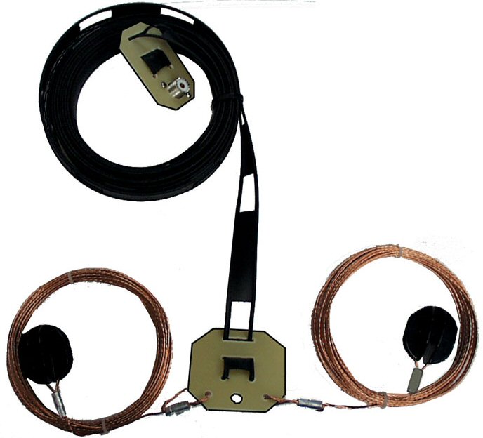
    Firstly I wanted to find out for myself if the folded dipole, terminated in the middle with a 450 ohm resistor, would be more quiet and still receive low level signals. So I made a rough hand sketch of two side loops with 21 meters of wire each side. I didn’t have proper antenna wire so I used electric fence wire – lots of that around. It is a multi-strand wire, silvery-looking, and it is very stiff so it must be steel or something. I bought a 10mm dowel, cut it into 220mm pieces and drilled 2mm holes near the ends for he wire to pass through. I purchased a random 25 watt 470 ohm resistor (I have no idea if it has inductance or what) and with electric fence crimp collars wired up the works in less than an hour. I’ll post some photos later. The balun is a problem as I don’t have a 9:1 balun available, so I used my standard 4:1 balun and I’m expecting some degradation because of that. I strung it from the highest point on the chimney pole to a roof eave in a slightly E-W direction.

    The photo shows the middle area of the antenna with the resistor on top and the balun below.btfd

    Comparing it to my MFJ Junior G5RV on-air (below the BTFD in the picture) it was giving very similar signal reports, and it was about 2 S-points quieter. This is enough to do some more scientific measurements and make some refinements, like replacing the balun. Initial impressions were very favourable and I’ll keep you posted.

  • Useful Info – Aeronautical Frequencies

    Aeronautical Radio Frequencies used in South Africa

    HF Communication – (108.000 – 117.975 MHz, Mode = AM)
    Frequency (MHz) Place Purpose / Description Contact
    8.933 O.R. Tambo Intl. Johannesburg, FAJS Springbok – Worldwide

    VHF Navigation – (108.000 – 117.975 MHz, Mode = AM)
    Frequency (MHz) Place Purpose / Description Contact
    115.200 O.R. Tambo Intl. Johannesburg, FAJS VHF Omni-directional Range

    VHF Communication – ( 118.000 – 136.975 MHz, Mode = AM )
    Frequency (MHz) Place Purpose / Description Contact or GPS Coordinates
    118.100 O.R. Tambo Intl. Johannesburg, FAJS Tower 1 – West ? S26°08’01.30” / E028°14’32.34”
    118.600 O.R. Tambo Intl. Johannesburg, FAJS Tower 2 S26°08’01.30” / E028°14’32.34”
    118.700 Rand Airport, Germiston Tower S26°14’31.12” / E28°09’04.88”
    119.600 Hoedspruit Airforce Base, FAHS Tower & Radar (1) S24°21.3’ / E031°03.0’
    120.350 Microland, Bapsfontein Microlight Airfield – no tower Hans Schouten – 083-442-4775
    120.600 Wonderboom, Pretoria North, FAWB Tower / Approach S25°39.0’ / E028°13.0
    120.800 Grand Central Tower
    121.300 Maputo, Mozambique
    121.400 O.R. Tambo Intl. Johannesburg, FAJS Jo’burg Director S26°08’01.30” / E028°14’32.34”
    121.500 Global Search & Rescue / Emergency
    121.650 Lanseria Intl., Midrand, FALA Ground S25°56’22.90″ / E27°55’32.07″
    121.700 O.R. Tambo Intl. Johannesburg, FAJS Clearance S26°08’01.30” / E028°14’32.34”
    121.750 Swartkop Airforce Base, Pretoria, FASK Ground (1)
    121.850 Waterkloof AFB, Pretoria, FAWK Ground
    121.900 O.R. Tambo Intl. Johannesburg, FAJS Ground S26°08’01.30” / E028°14’32.34”
    122.000 Krugersdorp
    122.300 Vanderbijlpark Radio
    122.400 Springs Tower
    122.650 O.R. Tambo Intl. Johannesburg, FAJS Apron Arrivals S26°08’01.30” / E028°14’32.34”
    122.700 Brakpan Radio / Tower
    123.050 O.R. Tambo Intl. Johannesburg, FAJS Apron Departures S26°08’01.30” / E028°14’32.34”
    123.200 Swartkop Airforce Base, Pretoria, FASK Tower (1)
    123.500 Parys S26°53’14” / E27°30’19”
    123.500 Witbank, FAWI S25°50.0’ / E029°11.6’
    123.700 O R Tambo Intl. Airport, Johannesburg Radar – West S26°08’01.30” / E028°14’32.34”
    123.750 O.R. Tambo Intl. Johannesburg, FAJS Comair Flight Ops S26°08’01.30” / E028°14’32.34”
    124.000 Lanseria Intl., Midrand, FALA Tower S25°56’22.90″ / E27°55’32.07″
    124.100 Waterkloof AFB, Pretoria, FAWK Tower
    124.250 Tracker Helicopter Stolen Vehicle recovery
    124.500 O.R. Tambo Intl. Johannesburg, FAJS Radar – South & East S26°08’01.30” / E028°14’32.34”
    124.800 Gauteng Uncontrolled Flying Area
    125.400 Heidelberg, Gauteng Johannesburg Special Rules – East
    125.800 O.R. Tambo Intl. Johannesburg, FAJS Johannesburg Special Rules – West S26°08’01.30” / E028°14’32.34”
    126.200 O.R. Tambo Intl. Johannesburg, FAJS Air Traffic Information Centre (ATIS) S26°08’01.30” / E028°14’32.34”
    126.400 Hoedspruit Airforce Base, FAHS Approach (1) S24°21.3’ / E031°03.0’
    126.700 O.R. Tambo Intl. Johannesburg, FAJS Area S26°08’01.30” / E028°14’32.34”
    127.400
    128.300 O.R. Tambo Intl. Johannesburg, FAJS S26°08’01.30” / E028°14’32.34”
    128.500 O.R. Tambo Intl. Johannesburg, FAJS Ground Crew
    128.900 O.R. Tambo Intl. Johannesburg, FAJS Common traffic advisory (CTA)
    129.100 O.R. Tambo Intl. Johannesburg, FAJS ? East
    130.250 O.R. Tambo Intl. Johannesburg, FAJS Ground Crew (SB Tarmac?)
    130.700 O.R. Tambo Intl. Johannesburg, FAJS Aircraft Servicing
    130.800 O.R. Tambo Intl. Johannesburg, FAJS Passenger Control ?
    130.850 O.R. Tambo Intl. Johannesburg, FAJS Freight Control
    131.200 O.R. Tambo Intl. Johannesburg, FAJS Passenger Control ?
    131.500 Harare, Zimbabwe
    131.725 ACARS Aircraft Telemetry Data
    133.200 Petit Airfield, Benoni North Radio – no tower Andy Casperson – 082-651-7317
    134.000 Waterkloof Info
    134.400 O.R. Tambo Intl. Johannesburg, FAJS Radar – North S26°08’01.30” / E028°14’32.34”
    135.500 Klipriver
    135.600 Rhinopark

    Notes: 1.) Unlicensed Military Aerodrome – to be used in emergency only.
    LINK: Download South African Airport Charts

  • Useful Info – 29MHz Band

    The 29 MHz Band is allocated in SA to Short Range Business Communication – (29.7100 – 29.9850 MHz)

    Channel Frequency (MHz) MODE Purpose / Description Users
    01 29.7100 AM Mobile
    02 29.7225 AM Mobile
    03 29.7350 AM Mobile
    04 29.7475 AM/SSB Civil Defense 1 ###
    05 29.7600 AM Mobile (Ch. 4 of the 4WDC)
    06 29.7725 AM Marine Channel ‘B’ or 2 – General purpose (Sea and Inland) (Ch. 5 of the 4WDC)
    07 29.7850 AM Mobile
    08 29.7975 AM Mobile
    09 29.8100 AM Mobile
    10 29.8225 AM/SSB Civil Defense 3 ### (Ch. 3 of the 4WDC)
    11 29.8350 AM Mobile
    12 29.8475 AM/SSB Civil Defense Main ###
    13 29.8600 AM Mobile
    14 29.8725 AM Mobile (Ch. 2 of 4WDC, ATVC)
    15 29.8850 AM Mobile
    16 29.8975 AM Mobile (Ch. 1 of the 4WDC)
    17 29.9100 AM Mobile
    18 29.9225 AM Rural Fire Fighting ###
    19 29.9350 AM Marine Channel ‘A’ or 1 – Emergency / Calling Channel (Ch. 5 of the 4WDC)
    20 29.9475 AM/SSB Civil Defense 2 ###
    21 29.9600 AM Mobile
    22 29.9725 AM Marine Channel ‘C’ or 3 – General purpose (Sea and Inland)
    23 29.9850 AM/SSB Civil Defense 4 ###

  • Useful Info – CB Frequency Chart

    The 27 MHz Citizen Band (CB) is allocated in South Africa on (27.185 – 27.275 MHz) as follows:
    Channel Frequency (MHz) MODE
    19 27.185 AM
    20 27.205 AM
    21 27.215 AM
    22 27.225 AM
    23 27.255 AM
    24 27.235 SSB
    25 27.245 SSB
    26 27.265 SSB
    27 27.275 SSB

    Please Note: Only channel 19 to 27 are legal in South Africa.
    Maximum AM RF Output Power = 4 Watts RF
    Maximum SSB RF Output Power = 12 Watts RF Peak Power

    Allocations in other countries vary but this seems to me the general direction:

    CHANNEL FREQUENCY CHANNEL FREQUENCY
    1 26.965 MHz 21 27.215 MHz
    2 26.975 MHz 22 27.225 MHz
    3 26.985 MHz 23 27.255 MHz
    4 27.005 MHz 24 27.235 MHz
    5 27.015 MHz 25 27.245 MHz
    6 27.025 MHz 26 27.265 MHz
    7 27.035 MHz 27 27.275 MHz
    8 27.055 MHz 28 27.285 MHz
    9 27.065 MHz 29 27.295 MHz
    10 27.075 MHz 30 27.305 MHz
    11 27.085 MHz 31 27.315 MHz
    12 27.105 MHz 32 27.325 MHz
    13 27.115 MHz 33 27.335 MHz
    14 27.125 MHz 34 27.345 MHz
    15 27.135 MHz 35 27.355 MHz
    16 27.155 MHz 36 27.365 MHz
    17 27.165 MHz 37 27.375 MHz
    18 27.175 MHz 38 27.385 MHz
    19 27.185 MHz 39 27.395 MHz
    20 27.205 MHz 40 27.405 MHz

  • Huisbesoek: ZS6UT Ed Willers

    Ed Willers ZS6UT
    Ed Willers ZS6UT
    I had the privilege of visiting Ed Willers ZS6UT at him temporary QTH in Faerie Glen recently. It is always a privilege to meet one of your fellow hams in person, and Ed was no exception.

    The background is as follows: You will read about the noise (QRN QRM) at my QTH, and my attempts to reduce it to lesser levels. I’ve tried just about everything. I’ve been offered a “noise cancelling speaker” by OM Sam ZS6___ who runs Radio Accessories and is a good friend. I’ve put tons of ferrite beads on every wire in and around the shack. I’ve made good earths. Everything helps a little but, but nothing makes a huge improvement.

    Except the literature on Small Magnetic Loop Antennas keeps on popping up. Everybody seems to say that they are small (about the size of a bicycle wheel) but that – for their size – they perform quite well under noisy conditions. And in true ham fashion I start phoning around. Not too long and OM Hans Kappetijn ZS6KR gives me the number of Ed ZS6UT, who was keen to show me what he had done.

    So I popped in for a quick visit. Ed runs a very nice shack and while he is in a temporary QTH he hasn’t installed his magloop. Instead he depends on a multiband vertical and a 80m horizontal loop. He jokingly shows me how he used his fishing rod and a car spark plug to get some fishing line into a bluegum tree. I was surprised by how quiet the loop is in comparison to the vertical. He has a vacuum cap that he is going to use on his small magnetic loop as soon as he can put it up. Awesome item. After Ed’s advice I now know exactly what I should be looking for.

    Thanks for the hospitality Ed. We’re going to cook the bands with our loops.