Category: My Tools

  • Measuring the QRPp’s Isn’t Easy

    SWR Detectors
    SWR Detectors

    Interesting how a development in one area of this hobby can force a sudden change of direction to explore some new areas. I’ve been happily experimenting with my Hans Summers Ultimate 3S kit when I realised that I could band-hop and get a picture of propagation conditions updated every 30 minutes or so. Cool idea.

    But band-hopping requires a multiband antenna. Alternatively a tuner or something to adjust the U3S (which has quite a robust albeit low power output) to the piece of wet string hanging out the window. Even then, one may never know exactly how well you are getting out, and therefore whether your propagation forecast is accurate.

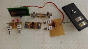
    Thus the sudden change in direction: I want to measure exactly how much RF is going down the cable to the antenna. This should be easy, right? A quick search on Google brings up dozens of very good kits and circuits, and I dive headlong into the challenge. That was a few weeks ago already. And I learnt a painful lesson: There are not a lot of options available for the QRPp operator.

    Let me be honest, many of the circuits and kits I saw were designed for the American market where they must handle kilowatts with a minimum scale of 100 watts. But when you start talking in the milliwatt region there is a big void. I spent hours and hours winding toroids, soldering up detector boards, wasting tons of paper taking meticulous readings, all in the 5 watts plus region. But I couldn’t get things to work in the 150mW and less region where the Ultimate 3S is working.

    So here is the challenge: Does anybody have a working circuit or plan for a QRPp SWR / Power meter? Drop me an email and I can share some of the ideas I have already tried, but I’m desperate for some new ideas.

    73s de Leon ZR6LU from Johannesburg 0825735580

  • Ham Radio Maps of ITU and CQ Regions

    Ham Radio Maps
    Ham Radio Maps
    I found these really useful maps of the world showing ITU and CQ regions on the website of EI8IC [click here].

    They will make a nice poster on your wall and helps to identify those hard to remember zones.

    Do you have other maps or charts you might want to tell us about?

  • Measurements Abound

    Major_MTD72
    Major_MTD72
    My radio and antenna collection is finally getting some rest, and my focus for this month has been power. Yes, getting enough 12 volts into all the boxes. My original Yaesu FP-707 Power Supply (the one that originally came with my FT-707) went Missing-In-Action (yup we live in South Africa) during the moves from my old house to my new house, and all I could find to use temporally was a FP-12 – a nice but slightly underpowered 12 Amp power supply.

    Now “underpowered” is an interesting statement, as I didn’t have any way to actually measure the current and voltage outputs of my power supplies. Initially, while I was fixing old radios and pulling wire antennas around, it didn’t really matter if I was slightly subjective about my power and a few amps here or there wasn’t enough to worry about. Even a standard hobby multi-meter (DMM) can read 10 Amps and that was good enough, initially.

    But gradually the need arose for more accurate measurements. Reading voltage was easy on the DMM, but reading up to 10 Amps for short bursts with the same DMM was just not good enough. So I shopped around and I came across the most useful little meter by the Major-Tech brand [click here] which reads out a digital 0-20 Amps with the relative ease of plugging in a fuse. Yup, as you can see from the picture it has a dongle the size of a screw driver handle with a nice digital read-out, connected to a measuring pad with a short wire. Now, this little beauty (an adapter for easy current measurement on blade type fuse connectors for cars) plugs into any blade-type fuse holder. Imagine that – I could actually see how much current I was pulling from my car battery without making any cuts or connections to the wiring AT ALL! All I did was find the cigarette lighter fuse, pull out the fuse and plug in this little monster – and there I had a direct, real time read-out of current.

    Major_MTD72
    Major_MTD72
    While it is a little pricey off the bat, this became less of an issue as its usefulness was soon expanded to do duty into other territories. Firstly, the adapter clips open to reveal a sense wire of about 3cm long. If you want to read higher ranges, just solder your sense wires a little bit closer to each other on this sense wire, and obviously re-calibrate (display is fixed at 0 – 20 whatevers). I’ve set mine now to read 0-40 Amps, but understand in my case I have to double the reading, so if I read 8 Amps I know it is 16 Amps.

    The second change is to solder two connecting wires to the two measuring spades (see first photo). I use heavy duty chocolate strip connectors for making temporary connections around the shack, and so now I can insert this baby in line with any power line for an extended period of time if I wish, making lots of measurements. A hobbyist’s dream tool!

    I bought mine from Mica but I’m sure any Major-Tech supplier can order one for you, or you can buy on-line. Enjooy!